
Generating analog signals with the Arduino microcontroller using PWM.
The pages in this section explain how to use an arduino to output a particular voltage or repetitive waveform.
Simple Pulse Width Modulation
Start here. Basics of using pulse width modulation to produce an analog signal or voltage. You will see how PWM works and how you can use it to control the brightness of an LED or speed of a motor.
Pulse Width Modulation to generate a voltage
Using a simple RC filter to smooth the PWM signal and give a dc voltage out
More advanced PWM
PWM: PWM Modes, higher frequencies, filtering and buffering.
Characteristic testing
Using an arduino to output a voltage and measure the response of a component or circuit
Measuring a mass
An example showing how a suitable waveform can be used to measure mass using inertia.
PWM for Digital to Analog conversion
The process of generating a voltage or repetitive pulse train corresponding to a particular numerical value is called Digital to Analog Conversion. (DAC)
While some Arduino's (eg the ESP32 series) incorporate a dedicated circuit to do this digital to analog conversion, many do not.
However all arduino's are capable of generating a pulse train whose AVERAGE value corresponds to a number.
(Pulse width modulation, or "PWM")
Simple Pulse Width Modulation
When we use analogWrite(n) to a PWM capable * digital output pin it gives a pulse wave whose average voltage depends on the value written (n) and the high and low voltage levels of the output pin.
How does this work?
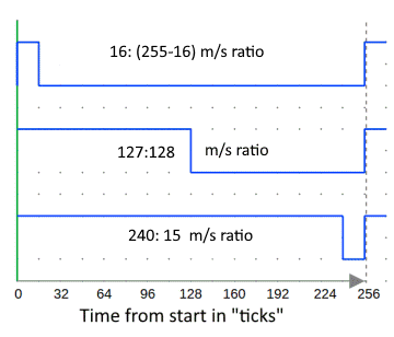
The diagram shows the output from a PWM compatible digital output pin when we use analogWrite(16), analogWrite(127) or analogWrite(240)
PWM capable: On some microcontrollers PWM is only available on selected pins. Please consider the pinout diagram of your board to find out which ones you can use for PWM. They are denoted with a tilde sign (~).
The average output voltage is (approximately - see note)
Vout average = Vcc * n / 255
so for an Arduino with a 5V Vcc we will get
- analogWrite(0) gives 5 *0 / 255 = 0.00V
- analogWrite(16) gives 5 *16 / 255 = 0.314V
- analogWrite(128) gives 5 * 127 / 255 = 2.5V
- analogWrite(240) gives 5 * 240 / 255 = 4.705V
- analogWrite(255) gives 5 *255 / 255 = 5.00V
NOTE: the actual average voltage will also depend on the high and low value voltages from the output pin.
The ATMEL data sheet for the 328 processor (27.4.8, pages 412 & 413, figures 27.159 - 27.162) show a digital output pin has an internal resistance of about 30 ohms. So provided we dont load the pin the output Vol will be near 0V, and Voh near Vcc.
Simple PWM to dim an LED
/*
This example shows how to fade an LED on pin 9 using the analogWrite() function.
Code is a modified version of the arduino "Fade" example https://www.arduino.cc/en/Tutorial/BuiltInExamples/Fade
LED is connected to pin 9 and via a resistor of about 470 ohms (https://www.skillbank.co.uk/arduino/led.htm) to ground
*/
int led = 9; // the PWM pin the LED is attached to: On a Uno and many others pin 9 is PWM capable
int brightness = 255; // how bright the LED is at the start
int fadeAmount = 5; // how many points to fade the LED by
void setup() {
pinMode(led, OUTPUT);
}
void loop() {
brightness = brightness - fadeAmount; // change the brightness each time through the loop:
analogWrite(led, brightness); // set the brightness of the LED
delay(30); //
}
The PWM signal will actually flash the LED at 490Hz, (or about 2msec) but because your eyes dont respond that fast the effect is averaged out, so you just perceive the average brightness.
Control a motor with PWM
Your PWM signal can also be used to good effect to control the speed of a dc motor.
See how to use PWM to control the speed of a motor on this page
Advantages and disadvantages of Pulse Width Modulation for control
For many applications such as control of the brightness of a lamp or the speed of a motor simple PWM is fine, provided the frequency is suitable.
- If you try to use a voltage level to control an LED it will be non-linear because at low voltages the LED will not have enough voltage to work at all.
- If you try to use a voltage level to control a dc motor the low voltages will not provide enough torque for the motor to turn.
However there can also be disadvantages.
- Switching a supply to an inductive or capacitive load causes surges that can be damaging
- Driving a mechanical device - motor, solenoid etc - from PWM can result in audible sound at the PWM frequency