
John Errington's Experiments with an Arduino
Choosing and using operational amplifiers for your Arduino projects
Introduction: measuring voltages with an Arduino
Operational amplifiers are simply devices that amplify the difference between two inputs. However these simple devices can be used in combination to create many useful circuits - even very powerful ANALOG computers! If you want to measure a signal voltage with an Arduino, you may face some of the issues described here; often a simple circuit using an operational amplifier can help.
 Lets look at these problem issues.
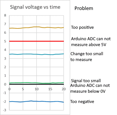
The Arduino Uno has ADC inputs that can measure voltages in the range 0 to 5V.
(other ranges are available on different versions)
So if your signal is outside this range - as the orange and blue lines on this diagram - you cant measure it directly. An inverting amplifier will let you produce a positive voltage of the same value, which you can then measure.
Also your signal may be too small to measure; (green line) in which case a non-inverting amplifier as described below can help. So if the signal is changing between 0.1 and 0.2V an amplifier with a gain of 20 will give a signal in the range 2 - 4v which matches the measurement range of the Arduino.
The cyan line is a bit different. Suppose the signal is changing between 3.4 and 3.6V - so a change of 0.2V; we could amplify it by ten - but then it would be changing between 34V and 36V - still no good. However using a difference amplifier (see below) we can take the 3.4 - 3.6, SUBTRACT 3.2, and multiply by ten - giving a nicely measureable signal in the range 2 - 4 Volts.
The operational amplifier circuits described below will allow you to perform this "signal conditioning".
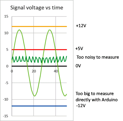
Other possible issues are that your signal is just too big to measure directly , and will need to be reduced in size, or "attenuated" as for the light green sine wave shown here;
Or the signal has a lot of noise which you will need to remove by "filtering".
We will look at how to use op amps to attenuate or filter a signal later.
NOTE: in most cases the signal to be measured must lie within the limits of the supply to the arduino or op amp being used to measure it. The +12v and -12V lines show the range of inputs you can use with an op amp powered by ± 15V.
On this page I'll introduce some important terms relating to op amps. However to get you where you want to be, here are some bookmarks.
What is an "Op Amp" If op amps are new to you, or just to refresh your memory, start here
Basic circuits: preparing a signal for measurement
Choosing an op amp for your project:
A "short list" of op amps for most applications
Using op amps in your project:
Single or split supply - and "rail to rail" operation.
Important characteristics explained
Further reading:
What is an Op Amp?
 An Operational Amplifier is .. an amplifier; however it has special characteristics that make it very easy to design circuits for particular applications.
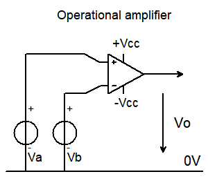
Fundamentally it takes two inputs, shown here as Va, Vb, and gives an output voltage Vo which is bigger than the DIFFERENCE between Va and Vb.
Vo = Avol (Va - Vb) where Avol is the "open loop voltage gain" of the amplifier
An "ideal" operational amplifier is a differential amplifier with the following characteristics:
it has
- infinite gain
- infinite input impedance (no current into input terminals)
- zero output impedance (no current limit on the output)
- infinite bandwidth (no limit on speed of response)
There are a few more minor "tweaks" we will introduce later but .. these four, with an understanding of Ohms Law, allow us to design and understand op amp circuits very easily - as you will see in the basic circuits that are described below.
NB: to simplify schematic diagrams the power supply connections to op amps may sometimes be omitted from the diagram - as in those that follow - or be shown seperately. But of course they do need power supplies!
Basic Circuits
Comparator.
A "comparator" compares two input voltages and gives an output of +Vcc if Va>Vb and -Vcc otherwise.
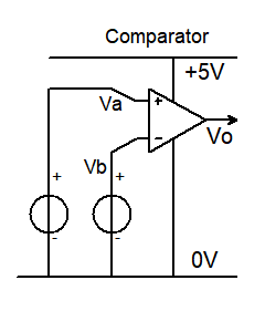
Typically a comparator is used to provide a digital output from an analog input. So we use a single supply as shown here.
Remember for an ideal op amp V0 = "infinity" times Va - Vb
however the output can not go higher than +Vcc, or lower than -Vcc, so here its limited to +5V or 0V
so if Va > Vb Vo = 5V; and if Va !> Vb Vo=0V
This allows us to give a logic level change if an input voltage Va exceeds a threshold voltage Vb.
Comparators are an important part of an ADC converter.
For many reasons op amps dont make great comparators, and its better where possible to use a purpose built comparator.
Unity gain buffer.
A "unity gain buffer" gives an output voltage that is the same as the input voltage
"Big deal", you may say. The important thing is it takes NO current from the input. It can be used to measure voltages without placing a load on the circuit being measured. Lets look at how it works.
Analysis: 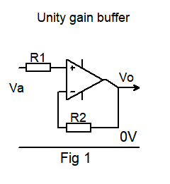
The unity gain buffer is very easy to analyse, based just on the characteristics of an ideal op amp.
As the amplifier has infinite gain
from #1: - the difference voltage between the + and - inputs must be zero.
R1 and R2 just provide protection to the amplifier inputs. "No" current flows through them.
so Vo = Va
What use is an amplifier with a gain of 1?
Well, remember 2: and 3: above: it has an infinite input impedance and zero output impedance.
Non-inverting amplifier
Like the unity gain buffer, this circuit does not load the input - but does provide a precise amount of voltage gain, set by resistors R1 & R2.
Vout = Vin (R2 + R1 / R1) or Vout / Vin = 1 + (R2 / R1)
The input resistance is VERY HIGH (ideally "infinite")
Analysis: Remember, for any finite voltage at the output the difference voltage at the input must be zero.
Lets analyse this circuit just using the ideal op amp characteristics and you will see how easy it is. We'll use real numbers.
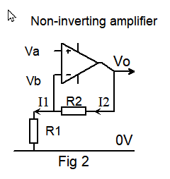
Suppose Vo = 10V and R1=2k, R2 = 18k
R1 + R2 = 20k so a current of 10V / 20k = 0.5mA flows through the resistor chain.
NONE of that current flows into the inverting input. (2:) ( I2 = I1 )
So the voltage across R1 is 0.5mA * 2k = 1V
but from 1: Vb = Va .. therefore the voltage gain Vo / Va = 10V / 1V = 10.
We can ignore any loading effect the resistor chain places on the output because of 3:
And from 4: any change at the input will IMMEDIATELY effect the output with NO delay or phase change.
Inverting amplifier
This circuit allows us to convert a negative voltage to a positive one (or vice versa) for measurement.
Vout = - Vin R2 / R1 or Vout / Vin = - R2/R1 ( Note: this formula is not the same as for the non-inverting amplifier)
The input resistance Rin is just R1. However with modern op amps we can use large value resistors.
Analysis: once again, Remember (1:) the difference voltage between the + and - inputs must be zero: so
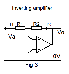 the junction of R1 and R2 is at 0V.
(we call this a "virtual earth")
Vo = I2 R2
Also (2:) no current flows into the input terminals - so I1 = I2
Va = - I1 R1 = - I2 R1.
Vo / Va = I2 R2 / - I2 R1 = - R2 / R1
Important note: Unlike the circuits of Fig 1 and Fig 2 this circuit involves a current flowing through the input circuit, so the gain WILL depend on the source resistance. The usual way to avoid this is to use a unity gain buffer at the input.
Difference amplifier
This simply measures the DIFFERENCE between the two inputs and multiplies it by a gain factor.
So V0 = (Vb - Va) (R2/R1) ;
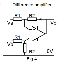
If R2 = R1 the output voltage is the DIFFERENCE between the two input voltages.
By choosing different values we can add a bit of gain;
so if R2 = 10M and R1 = 1M we will have a gain of ten.
Now the input resistance for this circuit is just R1 + R2
so if you dont want to load the circuit you are measuring R1 and R2 need to be large - and you will need to choose an op amp with a * low input bias current. (more on this later)
Instrumentation amplifier
If we add a non-inverting amplifier at each input of the difference amplifier we overcome the limitation of the input resistance. An amplifier built like this has lots of uses, and some special properties. You will find the full circuit and description on the next page.
But our real world op amps are not "ideal"
No, but modern op amps can be a very good approximation to an "ideal" op amp provided you choose the right one for your application. As an example lets look at possibly the most important feature - infinite gain. The uA709 - an early IC op amp - had an "open loop voltage gain" of 10,000. Modern op amps may have gains over 1 million. The ubiquitous "741" also has poor performance when compared with more modern op amps - see the "747" - a dual 741 - in the table below.
Real world operational amplifiers do however have limitations; for example
- the output voltage cannot exceed the supply voltages; and
- the output resistance, although low, does impose a limit on the current they can supply.
We will add some "tweaks" to our ideal op amp specification to reflect their real world limitations:
In no particular order: (these terms are explained below)
- Zero input offset voltage
- Zero noise
- Zero input bias current
- Infinite Common Mode Rejection Ratio
- Infinite Power Supply Rejection Ratio.
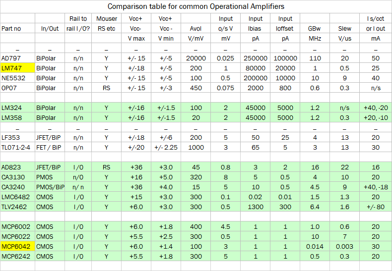
In the table that follows you will find values of the most important characteristics for some "real world" op amps, to guide you in choosing one for your project. To "short-cut" this for simple applications, just go straight to the recommendations below.
Different "flavours" of op amps
To provide performance characteristics to suit a wide renge of applications op amps are made using different transistor technologies (Bipolar, JFET or MOSFET). Each has its own benefits and limitations; for example bipolar op amps may have higher gain, lower input offset voltage, fater response, and be more robust. MOSFET op amps can provide "rail to rail" operation (but see below) with very low input bias currents and high (almost infinite) input resistance (but some input capacitance). Some op amps combine FET and bipolar sections for the "best of both worlds".
However to decide if a particular op amp is suitable for your application you would generally need to consult the data sheets.
A "short list" of popular op amps
 There are so many op amps you could never choose the "right" one. So here is a list I've compiled that will cover most common applications. I have tested them all. The criteria I've used in making this selection is they must be:
- Readily available from different sources (eg Mouser, RS Components )
- Available in a DIP package suitable for breadboards or sockets ( for when you blow them up ).
- In common use and inexpensive (mostly less than $1)
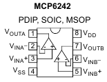
- And mostly two op amps in a single 8 pin package (as shown here) - although usually there will be other options.
NOTES::
The upper half of the table lists op amps with a bipolar input circuit - so they generally do NOT accept rail - rail inputs or outputs. You will see they have generally lower input offset voltage and MUCH higher input bias current than the FET input op amps in the lower half.
MOS input stages allow extremely high input impedances, while MOS output stages allow ALMOST rail-rail output voltages.
I've highlighted the LM747 - a dual 741. A popular choice it really has little to recommend it as compared with more modern op amps.
The devices in the green sections are suitable for single-supply operation. However few op amps will work with supplies much below 5V.
The MCP6042 is a micropower op amp intended for very low frequency applications - hence the GBw of only 14kHz - its NOT a misprint!
Recommendations
For a single supply driven from your Arduino's 5V or 3.3V supply,
the MPC6002 is ususlly a good choice; if you need a faster response use the MPC6022.
For dual supply running from ±5V to ±15V
The TL072 is usually suitable. For more demanding applications the AD823 may be a good choice.
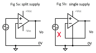
Single or split supply, and "rail to rail"?
The most important criterion is that the inputs to your circuit must not exceed the bounds of the power supplies.
So for example in Fig 5a if you are using +15V - 15V for the supply then you can reasonably apply a 10 volt PEAK sinewave and you will see the same at the output.
You can use the SAME op amp with a single supply (Fig 5b) +30V - 0V
... and it wont work - and you will likely damage the IC - because the negative excursion of the AC input is outside the range of the supplies.
Bipolar op amps generally need a bit of "headroom" so for example in Fig 5a with ±15V supplies your AC should be restricted to say 12V pk - pk.
A split supply doesnt need to be symmetrical as long as the inputs and expected outputs stay within the bounds of the supplies.
Generally CMOS op amps can happily accept "rail to rail" inputs. However when you read it offers rail-rail outputs you should be careful. The circuit will give outputs a few mV above zero or below the +Vcc supply - but only with a very high impedance load.
Important characteristics explained
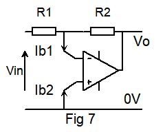
Input Bias current, Input Offset current, Input Offset voltage, and "headroom"
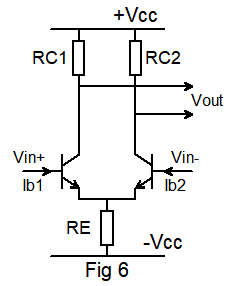
Fig 6 represents the input stage of a conventional bipolar op amp. You can see that the inputs Vin+, Vin- need to provide base current Ib1, Ib2 for the transistors. This is the input bias current.
If the gains of the transistors are not identical they will not take the same base current. The difference between them is the input offset current.
Suppose Vin+ = Vin- ; then Vout SHOULD be zero. However if the transistors are not perfectly matched there will be a difference in their Vbe - that is the input offset voltage.
"headroom"
Looking at this circuit you will see that if Vin+ or Vin- was at -Vcc the transistors would be turned off and the circuit could not work; most op amps require the input voltages to be well within the supply voltages - and in particular -
op amps with bipolar input stages - like this - generally need Vin to be about 3V clear of -Vcc or +Vcc.
Lets look at how these characteristics affect the operation of a real circuit.
Suppose we build a unity gain inverting amplifier that will allow us to use an Arduino to measure a voltage between 0 and -5V.
We know a voltmeter should not load the circuit it is measuring so we want a high input impedance.
 First we will use a "741" - half of an LM747. It has an input bias current of 0.08uA
We have resistors R1, R2 of 10M, which gives us a 10M input resistance. The voltage we measure will have an error because Ib1 is fed from a resistance of 5M (10M //10M) while Ib2 is fed from a zero resistance.
The error due to the input bias current of 0.08uA is Verror = 0.08uA * 5M = 0.4 volts!
Now lets replace the "741" with a TL071 - Ibias is 0.065nA; so Verror = 0.065nA * 5M = 0.3 millivolts!
However we must also take into account its input offset voltage - still only 3mV.
Gain Bandwidth product and Slew Rate
Both of these relate to the frequency response of the amplifier. Few op amps will have very wide bandwidth - mostly around 5 - 10MHz.
Suppose you build an amplifier using a NE5532, which has a gain-bandwidth product of 10MHz and set it for a gain of 100 the amplifier bandwidth will be 10MHz / 100 = 100kHz.
The slew rate is the speed at which the output voltage can change in response to an instantaneous step voltage at its input. Looking at the table you will see that to get a fast slew rate you need an amp with a good GBW product.
Faster is not always better
Very fast op amps like the AD797 above are useful in specific applications, but may prove less stable and prone to oscillate, sometimes needing careful decoupling and pc layout. Op amps with a GBW of 1 - 10 MHz are easier to work with, and for signals that are only changing slowly consider op amps with a gbw less than 1.
Further reading
The two sections that follow give a more detailed analysis and explanation of the use of op amps.
The differential amplifier
An operational amplifier is a differential (difference) amplifier with two inputs and one output. It can be shown in a diagram like this:
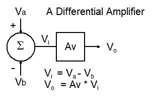
There are two voltage inputs:
- a "non-inverting" input Va
- an "inverting" input Vb.
The "summer" (circle symbol)
measures the DIFFERENCE voltage Va -Vb to give Vi;
The "gain block" (square box symbol)
amplifies Vi by Av - the "voltage gain".
So the output is Vo = Av * (Va - Vb)
However such a simple difference amplifier has a problem; for every amplifier the gain will be different depending on how the amplifier is built.
This problem can be solved by introducing "negative feedback" as explained below.
Introducing negative feedback
In 1934 Harry Black realised that by introducing "negative feedback" the behaviour of an amplifier could be controlled and stabilised.
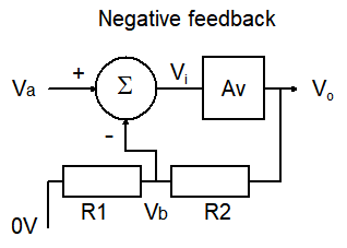
The voltage gain Vo / Va with negative feedback is ( R1+R2 ) / R1
Proof: (TL;DR) the resistor chain R2 R1 acts as a voltage divider so
Vb = Vo * R1 / R1+R2
Traditionally, to simplify the calculation, we call the amount fed back the "feedback faction" denoted β.
So β = R1 / R1+R2
Vo = Av ( Va - βVo ) so (Vo / Av) + βVo = Va
Vo / Va = Av/ 1+ β Av = 1 / ( (1/Av) + β) ... and if Av is large Vo / Va = 1 / β
So if Av is large the gain of this circuit will be Vo / Va = R1 + R2 / R1
and notice the gain now DOES NOT DEPEND on the gain Av of the amplifier itself, provided it is large enough - as with modern op amps.