
John Errington's Experiments with an Arduino
Precise voltage measurement with the Arduino microcontroller.
You can measure voltage with an Arduino ADC
Use an external reference attached to the AREF pin
Use an external reference when there IS no AREF pin!
How to convert your reading to voltage
The ATMEGA chip used on the Arduino has analog inputs that can be used to accurately measure voltage
The Arduino microcontroller is provided with a successive approximation type Analog to Digital converter (ADC) which has the following specification. References shown in brackets thus (2: 26.1) refer to sections of the AtMega 2560 data sheet.
(2: 26.1): ATMega328 and 32U4 have similar values.
Resolution 10-bits (i.e. 00 0000 00000 to 11 1111 1111 binary, or 0 - 1023 decimal)
Integral Non-linearity .. 1 LSB
Absolute Accuracy ± 2 LSB
Conversion Time 13 - 260 µs
Input resistance R_in =100M (2: 31.8)
Input resistance of Reference voltage R_ref = 32k (2: 31.8)
These specifications tell us the Arduino is capable of measuring voltages to an accuracy
of ± 2 LSB - so the maximum error is 2 * the LSB value
So the worst case accuracy of the converter is 2 / 1024 or 1 part in 512 i.e. 0.125%.
However the limit of the measurement accuracy depends on the voltage reference used.
The Arduino has its own voltage references - but they are not very accurate
The chip - depending on type - is provided with SOME of the following reference voltages (6)
DEFAULT: the default analog reference of 5 volts (on 5V Arduino boards) or 3.3 volts (on 3.3V Arduino boards)
INTERNAL: a built-in reference, equal to ABOUT 1.1 volts on the ATmega168 or ATmega328; also on the ESP32; and ABOUT 2.56 volts on the ATmega8 and 32U4 chip boards. This is produced internally by amplifying the 1.1V reference.
EXTERNAL: the voltage applied to the AREF pin (0 to 5V only).
(The MicroPro 32U4, NodeMCU and ESP32 do not have a pin for an external reference - see below for more information.)
However the accuracy of these "reference" voltages is very limited.
For example:
DEFAULT: depends on your computer power supply- AND the arduino board. Some have a protection diode that can drop Vcc to less than 4.5V
(7: 11.4.2) USB Vbus = 4.45V - 5.25V
(2: 31.8; 3: 26.7) Vint 1 = 1.10V actually 1.00 -- 1.20V
(2: 31.8; 4: 29.8) Vint 2 = 2.56V actually 2.40 -- 2.80V
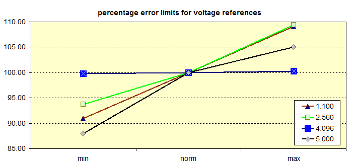
The accuracy of the reference against which the voltage is measured - using any of the above references - is at best only 5.25 - 5.0/5.0 * 100 = 5% - much worse than the 0.25% the ADC provides. Clearly if we wish to measure voltages to the accuracy provided by the Arduino the on-chip references are not good enough. The diagram below shows these errors as compared to a 4.096V reference described below.
Choosing the right reference for your measurements
For best results you should choose a reference that is just a little larger than the expected range of your unknown; If you're measuring from a potentiometric sensor then the DEFAULT is often ideal.
In other cases it may be less so. Let's look at our "magic voltmeter" that starts by measuring the 1.1V internal reference against Vcc. What is the number (n) we read?
n / 1.1 = 1024 / 5 .. .. so .. .. n = 1024 * 5 / 1.1 = 225 - or 0b00 1110 0001 - so we have lost two bits of resolution.
You should always try to ensure the range of voltages you are reading is a good match to the reference you use. So if you expect a maximum of 3V a 3.3V reference would be a good choice.
Using the external voltage reference input pin AREF.

If you connect the external reference voltage to the AREF pin through a protection resistor of 4k7 or more, it allows you to switch between external and internal reference voltages.
Normally the resistor will alter the voltage that gets used as the reference because there is an internal resistor of ABOUT 32K on the AREF pin. The two act as a voltage divider, so, for example, 5V applied through the resistor will yield 5 * 32 / (32 + 4.7) = ~4.4V at the AREF pin.
This reference will be a FRACTION of the +5V supply, not a precise voltage reference.
However, by connecting a shunt mode voltage regulator as shown here you can set the reference voltage accurately WITHOUT the hazard of damaging the arduino.
The LM4040AIZ2.5 (5) is a micropower SHUNT voltage reference diode, and if we connect this to the "5V" supply through a resistor, so that a current of >60 uA and <15mA flows through the diode, it provides a voltage of 2.50V with an accuracy of 0.25%
How it works:
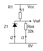
Lets look at the currents flowing; 1: Vcc=5V
R1 has (5V - 2.5V = 2.5V ) across it so (if we choose R1=4k7 )
i1 = (2.5 / 4k7) which gives 530 microamps.
Rint has 2.50 V across it so i3 = 2.5 / 32 = 80 microamps.
This leaves 530 - 80 = 450 microamps for the regulator.
Now designing for Vcc=3.3V
R1 has (3.3V - 2.5V = 0.8V ) across it so
( if we choose R1= 1k0 ) i1 = ( 0.8V / 1k0) which gives 800 microamps.
Rint has 2.50 V across it so i3 = 2.5 / 32 = 80 microamps.
This leaves 800 - 80 = 720 microamps for the regulator.
You can use other regulator voltages by choosing a suitable value for R1.
CAUTION: Don't use anything less than 0V or more than 5V for external reference voltage on the AREF pin!
If you're applying an external reference voltage to the AREF pin without a resistor for protection , you must set the analog reference to EXTERNAL before calling analogRead(). Otherwise, you will short together the active reference voltage (internally generated) and the voltage on the AREF pin, possibly damaging the microcontroller on your Arduino board.
Another approach is to use an external reference voltage for continuous calibration
Some Arduinos dont provide a pin for an external voltage reference. So for example the Nano does, the Micro does not.
An alternative to using an external reference is to use the DEFAULT supply voltage as a reference - but then read the voltage of an accurate reference to calibrate it while in use.
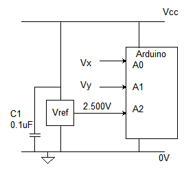
The diagram shows a LT1460-2.5 SERIES voltage reference providing 2.500 +- 0.1% connected to A2.
Now using the 5V supply "DEFAULT" to measure both the reference and your unknown voltage(s) we apply a simple correction to get a precise value.
if nX is the reading for Vx; nRef the reading for vRef then Vx(true) = Vref * nx / nRef.
Lets work with numbers: Suppose the "precise" reference of 2.500V is read as 883;
then if your unknown measures 724 the true value is 2.500 * 727 / 883 = 2.058 volts.
Here is a sketch that does all this for you, and averages the readings for better resolution and noise reduction.
How to convert your ADC reading to voltage
The Arduino range of microcontrollers provides analog inputs that can be used to measure voltage. We can use this to build a voltmeter.
The analogRead() function reads the voltage and converts it to a number between 0 and 1023. (or 4095)
Arduino tutorial (1) http://arduino.cc/en/Tutorial/ReadAnalogVoltage has this example:
// read the input on analog pin 0:
int sensorValue = analogRead(A0);
// Convert the ADC reading (which goes from 0 - 1023) to a voltage reading (0 - 5V):
float voltage = sensorValue * (5.0 / 1023.0);
This is WRONG! For a better result use (sensorValue + 0.5) * 5.0 / 1024.0 - see explanation here
This leads us to believe that a reading of 0 corresponds to an input of 0.000V; and 1023 corresponds to an input voltage of 5.000 volts. This is not entirely true.
You can NEVER get an exact numerical reading of voltage. (or anything that isnt ALREADY a number)
All your ADC will tell you is the measured value to the limit of accuracy and resolution of your instrument.
So your 10 bit ADC with a reference of 5.000V (5000 mV) will give a measurement of V volts PLUS OR MINUS 2 LSB
and the LSB is 5000 / 1024 = 4.88mV so the voltage lies within a band of V PLUS OR MINUS 9mV.
See this page for a more detailed explanation
Now lets look at measuring other voltages
REFERENCES:
1: Arduino tutorial http://arduino.cc/en/Tutorial/ReadAnalogVoltage
2: ATmega datasheet Complete: http://www.atmel.com/devices/ATMEGA2560.aspx?tab=documents
3: ATmega 328 datasheet: https://www.microchip.com/wwwproducts/en/ATmega328
4: ATmega 32U4 datasheet: https://www.microchip.com/wwwproducts/en/ATmega32u4
5: Voltage reference datasheet www.ti.com/lit/ds/symlink/lm4040-n.pdf
6: Arduino reference: http://arduino.cc/en/Reference/AnalogReference
7: USB standard: https://www.usb3.com/whitepapers/USB%203%200%20(11132008)-final.pdf