
Experiments with an Arduino: Program design methodologies
Are advanced design methodologies useful for the Arduino?
During the last century there have been many different approaches to the design of programs for computing equipment. As computers became more powerful there was a need for advanced program design methodologies that would support the development and documentation of ever more sophisticated programs. (Yourdon, VDM, Z etc).
Simpler strategies: Top Down design, State Machine Diagrams, and Pseudocode
In my view methodologies developed in the early days of microprocessors are well suited to the design of programs for the Arduino; and its limited computing power is no disadvantage for the simple tasks it can perform. So we have at our disposal strategies of the 60's and 70's such as top down design and stepwise refinement, supported by flowcharts or state transition diagrams, and pseudocode.
I wont go into details of these methodologies - you can find plenty of references - but at this level I dont feel that a rigorous adherence to standards is necessarily beneficial. You will get the idea of them as we develop the program for our keypress simulator.
Top down design
Here the first stage is to clearly describe the task -initially in its simplest form - and importantly without any examination of how it will be achieved.
"there shall be a device which issues key codes to the PC in the same way as a keyboard"
Stepwise refinement
Thinking about the problem we realise that we will need to be able to control this process - turn it on or off - so we can regain control of the PC keyboard input. This immediately shows us the system will need to have two different phases or "states". In one the system will be passive, in the other issuing key codes. We will need to have a process which controls which of these states is in use.
State Machine Diagram
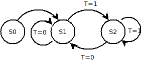
I find pictures very useful in imagining what is going on in the program. So lets create a state diagram for our key press simulator.

The diagram shows three states: States S1 and S2 form a loop. You will recognise that this structure maps well to the Arduino's basic "setup" and "loop" program sections.
At this stage we havent considered how changes between the states will occur, excpt that in our simple program S0 (setup) always passes control to S1, and some event causes a change from S1 -> S2 while another event changes S2 -> S1.
Lets develop our state diagram a bit further.
 (Diagrams drawn with Dia)
As before S0 passes control to S1.
If T is 1 the state will change to S2 or remain in S2.
When T=0 it will change state from S2 to S1 or remain in S1.
Flowcharts

At this stage we could draw a flowchart. Flowcharts can be very useful in showing the general way a complex piece of software works. I dont see any real benefit in using them for developing programs for the Arduino, as these are usually rather simple.
Disadvantages:
- They require a graphics program of some description which has its own learning curve. (I used Meesoft Diagram Designer). Although you CAN just use pencil and paper.
- They allow you to represent program structures that are not rigorous. This could prejudice testing in a complex program.
- The flow (as here) may not correspond to the state diagram
- The time taken in producing a flowchart could be used instead to produce better documentation.
I'd suggest effective use of Pseudocode is better at this point because if done correctly:
- It enforces rational program structures that will be mirrored by the final program
- The text is comprehensible to non-programmers
- It can be created in the same programming environment as your program, or with any good text editor.
What is Pseudocode?
Its a strategy for describing your program; a "halfway house" between a natural language description, which lacks rigor, and a programming language such as basic, C etc. The Arduino IDE supports programming in a language similar to C so it makes sense if your pseudocode uses the same format. There are no standards AFAIK but for me here are some important features:
Your pseudocode should:
- be accompanied by clear natural language explanations of what you intend
- use similar structures to the language in which your program will be written
- not be able to be mistaken for a finished program.
Here is a good introduction to Pseudocode
First level pseudocode for the keypress program.
**********************
Psudocode for program to use Arduino to generate keypress signals to a PC via the USB connection
The program has two main structures:
"setup" which is executed first; and "loop" which runs continuously thereafter
the program is to issue characters if a switch in "on", or flash an LED if its "off"
**********************
setup(){
prepare arduino connections for input, output and sending characters
}
loop(){
if switch is on {send characters} else {flash led}
}
Note there is no attempt at this stage to refine how the "send characters" and "flash led" tasks will be accomplished. That is a later stage in "stepwise refinement".
A bit more detail
As we intend to use a push button to control the system we need to look at how the operation of the switch will be handled to give it a "push for ON" - "push for OFF" action. We now ignore all the rest of the system and consider solely the "read switch" section. Note how the pseudocode and documentation mirrors the structures we are familiar with in C.
boolean read_switch() {
/* Check has switch value changed from 0 to 1, indicated by swVal > swOld; if so toggle the return value T. The push switch is wired from a pullup input pin to ground so when pressed (active) it will go from 1 to zero; so the initial value swOld is set to 1. Note our variables will need to be globals so they can be passed between this function and other parts of the program.
*/
read value of swVal from push button: test has it changed, and if so, how
if (swVal < swOld) { button is active (low) so toggle T and change swOld to zero }
if (swVal > swOld) { button has been released so change swOld to 1 }
return T;
}
Now lets go on to see how these techniques can help in designing our program.