
John Errington's Experiments with an Arduino
Voltage measurement with the Arduino board: Logging data
Having taken the required measurements we can now save data to a file on an SD card. For this project I am using a MEGA because the UNO has too little storage for global variables.
There are two main hardware options;
 An arduino shield, as shown here, which makes all the connections for you, and supports an ethernet port as well as the sd card. This allows readings to be continuously displayed in the form of a web page, as described below.
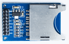
This shows an SD card interface which connects to the Arduino's SPI (serial peripheral interface).
Note the numbering for connectors and headers is different to the way IC sockets are numbered - its better to ignore the numbers and work from the labels. If you make a mistake you could damage the Arduino board.

The CS line is connected to one of the Arduino's digital outputs (53 on the Mega).
Here is my completed data logger using an Arduino Mega 2560 and Ethernet shield, which, following a reset:
- checks to see how often to take samples
- waits for a start signal, then repeatedly
- takes readings from two analog inputs,
- converts the values to voltages in mV
- stores readings to an SD card
- displays them on a remote PC via the ethernet
 Connections to Arduino
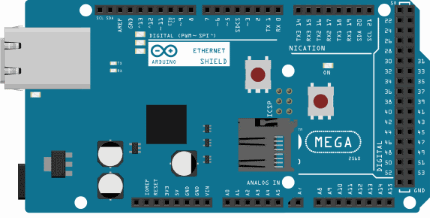
This figure shows the Arduino Mega board and Ethernet shield.
The schematic diagram for the analog input circuit with connections to A3, A2, logic inputs to D2 - D7, and supply connections to the +5V and 0V pins is shown below.
Note: Arduino communicates with both the W5100 and SD card on the Ethernet shield using the SPI bus (through the ICSP header). This is on digital pins 10, 11, 12, and 13 on the Uno and pins 50, 51, and 52 on the Mega. On both boards, pin 10 is used to select the W5100 and pin 4 for the SD card. These pins cannot be used for general I/O. On the Mega, the hardware SS pin, 53, is not used to select either the W5100 or the SD card, but it must be kept as an output or the SPI interface won't work.
Also you can not use A0, A1 (see below)
 S1a chooses an input range
0-2.5V or 0-25V for the V1 input
S1b signals to the program
to say which range is in use.
S2a /S2b perform the same function
for the V2 channel
Analog input circuit
This provides inputs that can be independently switched to select a voltage range of 0 - 2.5V or 0 - 25V. A two pole two way toggle switch selects the range and also signals to the Arduino to tell it which range is selected, so that the readings can be correctly formatted.
For this application an external 2.50V reference may be used, or if that level of accuracy is not required you can use the Mega's internal 2.56V reference (INTERNAL2V56).
Alternatively using a 4.096V reference would give ranges of 0-4V, 0-40V.
Explanation:
The input board is powered from the "5V" output from the arduino. When running from a USB supply this provides about 4.7V. The MCP6042 dual CMOS Op Amp is chosen because it can run from a single supply of 1.4V - 6.0V and provide an output swing from rail to rail. The 47k series resistor limits current to the input protection diodes.
Vz1 is a LM4040DIZ2.5 voltage reference. The 4k7 series resistor (5.0V - 2.5V = 2.5V
across it) provides a current of around 0.5mA to the regulator.
Why do we not use A0, A1?
The first experiments used these inputs and it was found impossible to calibrate the system correctly. Apparently the Ethernet card uses these two connections. A2 and A3 (or any of the other Analog inputs) work just fine.
Below: the completed unit in its box.
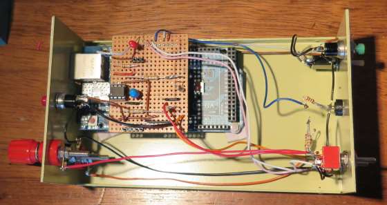
Construction:
R1 & R2 are "birds-nested" - mounted directly onto S1a (S2a for channel 2).
WHY? because they have a resistance of 9Mohm - so any leakage of current from the rest of the circuit would show at the input! Similarly, the circuit around R3, R4 and the non-inverting input pins of the MCP6042 need to be protected from stray current by keeping tracks short and board clean.
The remaining components are mounted on a small piece of veroboard (stripboard), which also supports the 2.50V reference. This fits neatly on top of the ethernet shield.
Right click here to get the sketch for the arduino IDE in zip format.