
John Errington's Experiments with an Arduino
Controlling DC motors and other high current devices
These circuits will also work to control anything that takes a bit more current -
powerful LEDs, heaters, relays and solenoids, or external circuits.
1: Unidirectional On/Off control
2: Proportional speed control without feedback
3: Using Pulse Width Modulation (PWM)
5: Bidirectional control - forward and reverse (PMDC motors only)
1: Unidirectional On/Off control
The simplest form of control system can often be achieved with a simple switch or relay. However it introduces two important factors; firstly, what happens when you remove the drive current to a motor.
 The windings of the motor are inductors, and store energy. When the supply to the inductor is interrupted the energy has nowhere to go, resulting in a negative voltage spike. The same applies to any inductive load such as a relay.
If you dont deal with this either the switch will arc (or if its a semiconductor it will fry) or the winding insulation will break down. The energy HAS to have somewhere to go.
This can be provided as shown here (left) by:
- adding a series capacitor C1and resistor R1 across the terminals (interference suppressor) OR
- by including a SNUBBING DIODE. This is wired so that it is reverse biased when the motor is running, but conducts when the negative spike begins, and "shorts it out".
The other factor to consider is that the motor may act as a generator if the shaft continues to spin.

Here the motor current is being switched by a transistor. The transistor is turned on by a positive voltage applied to R1. When this current ceases the mottor stops running. As before Diode D1 prevents a voltage spike that would damage the transistor.
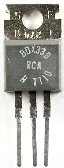
Suppliers often have selectors that let you choose the parameters you need. For this circuit I chose a power darlington type BDX33C (shown RIGHT) which has Icmax=10A, Vcemax=100V, Pt = 70W (on heat sink) and Hfe > 750.
We need a base current of 2A / 750 = 3mA so R1 = (5V - 1.4V) / 3mA = 1.2K
R2 is there to remove base current when TR1 is off - 10K is fine.
2: Proportional speed control without feedback
 The speed of a dc pm motor depends on the load, and the supply voltage, as shown here.
If the no-load speed is 10,000 rpm with a 10V supply, then it will run at 6000 rpm from a 6V supply.
So we can control the speed by reducing the voltage applied to the motor. This is easily done but has the disadvantage that the maximum available torque (driving power) is also reduced.
We'll come back to this graph.

Suppose we have a 12V supply. In the absence of a voltage V1 the darlington transistor TR1 (BDX33C again) is off, and no current flows. R1=10k makes certain there is no base current. R2 can be quite small - e.g. 470 ohms. Now if we apply a voltage - say 5V - to the input the emitter voltage will rise to 5 - 2*0.75 =3.5V and the motor will turn. Increase Vin, the motor voltage increases.
Connect Vin to the positive 12V supply and you get 12 - 1.5 = 10.5V at the motor.
The no-load speed is proportional to Vin. However, when the motor is running at low speeds lots of voltage is dropped across TR1, wasting battery power and producing lots of heat.
This approach works fine - but there is ... a better way.
3: Using Pulse Width Modulation (PWM)
 We can use the simple circuit we saw above to turn the motor supply on and off. If we do this repeatedly, we see the motor pulsing, going, stopping, going ..
If we speed it up the pulses smooth out, and the motor turns at a speed determined by the "mark to space ratio" of the pulses. So we can use "pulse width modulation" to control the motor speed. This has two main advantages; firstly that the full torque is available; and secondly that there is very little power dissipated in the control transistor, as it is always "fully on" or "fully off".
Each Arduino has pins that can directly generate a PWM signal, but
you may need to access the registers to choose an appropriate frequency for your application.
In this figure you can see a power MOSFET can be used to turn the motor on and off.
If driving from a digital circuit such as an arduino you will need to choose a logic level operated MOSFET!
The IRLZ44NPBF will take 40A and 55V - price 0.77p Mouser. R1=330 ohms, R2=10k
Sparkfun (and other suppliers) offer the FQP30N06L (60V 30A TO220 package) at around £0.80
Why have the resistors?
R1 (typically 220 ohm) with the gate capacitance dampens sharp edges that could cause oscillation.
R2 (typically 10k) ensures that if the control signal becomes open circuit the MOSFET will still turn off.
note - if R2 is on the gate side of R1 it forms a voltage divider that reduces the gate voltage.
This diagram shows some examples of different mark to space ratios.
"Mark" is when the signal is high, i.e. full voltage; and "space" when it is at zero.
The motor receives pulses at regular intervals, so when the mark to space ratio is very low (as shown left, 10%) the motor can be seen to "pulse" or vibrate. You can improve this by using faster shorter pulses. However every time the transistor switches some power is lost - so its a compromise, depending on the inertia of the load on the motor.
4: High side switching
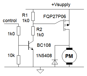 For many applications switching the ground rail is not suitable. For example automotives use the chassis ground as a common rail, and all devices are turned on or off by switching the positive supply. P Channel MOSFETs are well suited to this application - but need a gate voltage set from the positive rail. We can produce this very easily using a single transistor as shown here. The transistor also protects the controller - such as an arduino - from the higher voltages used to drive the load.
How it works:
Here the BC108 - or any other small signal NPN transistor - is controlled from an arduino output. With a logic 1 on the output pin its turned on, and the gate of the FET is pulled down, turning ON the FET and the motor (or other load)
The FQP27P06 is inexpensive and commonly available. In this configuration its suitable for voltages between around 8V - 40V; for other voltages you may need to adjust the values of R1 & R2 to keep Vgss in a safe range.
The 1N5408 protects the MOSFET from back EMF when the motor is turned off.
PWM: as for the previous circuit this can also be used for PWM control; however the gate of a MOSFET acts like a capacitor; for fast PWM its better to use a dedicated driver IC to provide the current needed to charge and discharge the gate capacitance.
5: Bidirectional control - forward and reverse
Only PMDC motors can be made to rotate in reverse by changing the polarity of the supply. To do this we need more switches, in the form of an "H Bridge". The diagram and truth table show the result of various switch positions.
| S4 | S3 | S2 | S1 | Result |
|---|---|---|---|---|
| 0 | 0 | 0 | X | open circuit: motor freewheeling |
| 0 | 0 | 1 | 0 | open circuit: motor freewheeling |
| X | X | 1 | 1 | short circuit! |
| 0 | 1 | 0 | 0 | open circuit: motor freewheeling |
| 0 | 1 | 0 | 1 | dynamic braking |
| 0 | 1 | 1 | 0 | drive reverse |
| 1 | 0 | 0 | 0 | open circuit: motor freewheeling |
| 1 | 0 | 0 | 1 | drive forward |
| 1 | 0 | 1 | 0 | dynamic braking |
| 1 | 1 | x | x | short circuit! |
Here you see the switches set for forward rotation. Current flows through S1, the motor, and to ground via S4.
If S1 and S2 (or S3, S4) are both closed there is a short circuit condition. This must be avoided.
When S1 and S3 (or S2 and S4) are both closed the motor is effectively "shorted out". The motor is then braked to a halt (regenerative braking).
With large motors and loads, and electronic switches (transistors of any form) this condition should also be avoided as excessive currents can destroy the H bridge.
Semiconductor H bridge ICs provide additional circuitry to prevent unwanted and damaging conditions. For "low power" applications the L298 IC can supply up to 4A at 40V. For more demanding applications an H bridge of discrete MOSFETs can be driven from an H bridge driver IC such as the HIP 4081.
H bridges are best suited to use in PWM systems as described above.
6: Control with feedback
When a load is applied to the motor it slows down to provide the needed torque. We can measure the speed continuously with a variety of sensors; for example we can use an optical encoder, hall sensor and magnet, or a tachogenerator. Perhaps the easiest way to do this is with a microcontroller such as an arduino. The controller senses the motor shaft speed, and changes the control signal to the motor to keep it at the chosen value.
See Servo control