
John Errington's Experiments with an Arduino
DC motors: How a motor works
 When you place two magnets close together, like poles repel and opposite poles attract. In the diagram the two outer magnets are fixed, and the central magnet is free to rotate on a shaft. The magnetic force will make the inner magnet rotate until the poles line up.
Now suppose the central magnet is an electromagnet. A switch (commutator) changes the polarity of the current so that S becomes N and N becomes S. The magnet and shaft continues to rotate clockwise, continually trying to bring N next to S. Thats a motor.
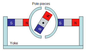
We can increase the strength of the magnetic field by "shorting out" the unused outer ends of the field magnets, in effect joining them together into one big strong magnet, with an iron "yoke".
Adding "pole pieces" further strengthens the field by keeping the air gap small.
This gives us a more powerful motor (more torque).
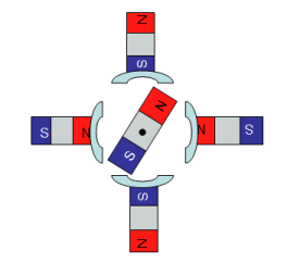 We can improve on this simple design by adding more magnets - more "poles". We can also add more windings on the armature. The "torque" T of a motor - the turning force - is given by T = Ia P Z Y / 2 pi A
where
Ia = armature current,
P = no of poles
Z = no of conductors,
Y = magnetic flux per pole
and A = number of parallel paths
Simply, adding more poles, more conductors on the armature, and maximizing the flux by keeping air gaps to a minimum gives more torque.
The speed N in rpm is given by N = 60 A (Vsupply -Ia Ra)/ P Y Z
More poles, more flux and more conductors results in a SLOWER but more powerful motor. Also you can see the speed (with no load) is dependent on the supply voltage.
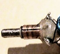
 This figure shows the commutator that does the "magic" of switching the current direction to keep the motor turning. It consists of two half cylinders of copper that connect to carbon brushes. As the shaft turns each is connected first to the +ve supply, then the -ve.
The commutator segments are insulated from the shaft, and connected to the windings on the "armature" - the bit that rotates.
If there are more windings more commutator segments are needed.
Build a simple motor
Follow the link above to see how to build a simple dc motor that will really work!
Types of motor:
Here we are going to look at four main types of motor - all DC operated because that makes them easy to control. Firstly, 1: the simple DC brush motor as described above; then a more recent development,2: the contactless DC motor. Then 3: the servomotor and 4: stepper motor, used where we need to control a position.
1: DC motor with brushes
 Common dc motors used in models, battery operated machine tools and similar applications, use a permanent magnet and yoke to provide the fixed magnetic field, and a winding are readily available in power ratings from milliwatts up to around 750W = 1hp. Modern magnetic materials allow these to be made in permanent magnet form.
In this picture you can see at the top, the motor housing, and below, the "armature" - the electromagnet wound on the core, the central shaft, and to the left, and enlarged (below, right) you can see the "commutator" that switches the direction of current.
 One disadvantage of these motors in high power applications is that the high currents cause heating in the armature - and because its inside it can be hard to keep the armature cool.
 Larger industrial dc motors such as those used in tramcars and also car starter motors often use electromagnets rather than permanent magnets, and are referred to as series, shunt, or compound wound depending on how the field electromagnet winding is connected.
Here you can se there are 4 field windings - giving 4 "poles" - and LOADS of windings on the armature.
1: casing (& yoke); 2: clutch and pinion gear 3: armature 4: field coils 5: brush carrier 6: solenoid
Generally the field and rotor windings are connected internally, so you will only see two wires coming from the motor casing.
2: Contactless (brushless) dc motors.
These work in a similar way to brushed dc motors. The commutator is replaced by electronic switchgear that does a similar job. The position of the shaft is sensed, usually with magnetic "Hall effect " sensors, and the output of these is used to turn on or off the current to the drive coils. This allows much greater flexibility in design. The windings are now on a fixed "stator" making for better efficiency as brush losses are eliminated.
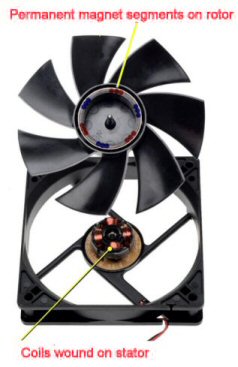
One application of "BLDC" motors is in equipment cooling fans, as they are not only much more reliable, but also virtually silent running. As you can see here the rotor is now outside the stator - we call this an "outrunner"
For higher power motors the number of windings (slots) on the stator is increased. As before this gives a slower but more powerful motor.
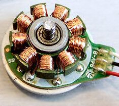 Small versions of this type of motor are found in DVD and hard drives. Generally the drive electronics is separate from the motor, especially for larger motors.
The only part subject to wear in these motors are the bearings that maintain shaft position.

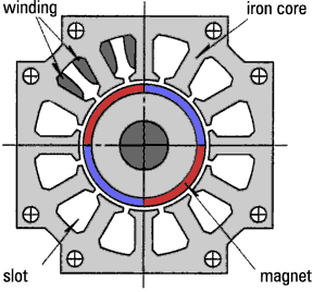 Left you can see a diagram of an outrunner style BLDC motor with 9 slots and 6 poles. There are three separate windings, blue, green, red. The rotor is made to turn by energising each winding in turn.
The diagram to the right shows an "inrunner" style motor with 12 slots and 4 poles. This style places the coils to the outside where its easier to keep them cool, and is used for larger motors.
3: Servomotor:
A servomotor (servo) consists of a motor - of any type - with sensors that measure the shaft rotation - and sometimes the shaft speed. This enables precise control of the shaft position.
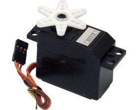 Simple servos (like the RC servo shown here) often use a DC motor with a potentiometer track to measure position. There are disadvantages to this. Firstly, the track may not be exactly linear, and in any event wear will in time worsen its precision; and secondly, the track will only allow measurement (and movement) over an angle of less than 360 degrees. However they are cheap and widely used in less demanding applications - such as model aircraft.
 For higher accuracy, and more robust and reliable control, optical encoders (which give a digital readout of position,) and magnetic (Hall effect) encoders (giving either analog or digital data) are used.
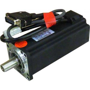
Here you can see a 200W (1/4hp) dc servomotor. The white connector is for 60V power, and the black & gold plug connects to an optical encoder.
The motor is a BLDC PM motor as described above, an inrunner style with 6 poles.
Servo motors are used when its important to know the position taken by the driven part. For example in an inkjet printer, the print head position is managed with a servo motor, while the paper feed is indexed by a stepper motor.
Servo systems can be prone to "judder" when they reach their desired position; and if this is a concern a stepper should be considered.
4: Stepper motor:
A stepper motor is another way of achieving accurate position control. Unlike the servomotor it is driven not by a dc voltage, but by pulses apllied to separate windings on the STATOR. The ROTOR is shaped like a gear wheel and a tooth is attracted by whichever winding is enegised. By energising one after another the rotor can be made to turn.
 So an important use of stepper motors is when something needs to be rotated through a particular angle, with each position clearly defined.
The stepper motor shown here is a 4-wire motor, and a single step will rotate the shaft by 1.8 degrees.
Its possible to achieve finer resolution by energising two windings simulataneously to get "half stepping". Also, by using sine waves rather than pulses a very fine control of position is achieved ("microstepping"). This can also allow continuous rotation.
When the drive to all coils is removed the stepper can freely rotate, and its position is then not known. Also an overstressed stepper, either from excessive load, or being driven too fast, will miss steps; and its position is then not known.
Stepper motors are best driven from purpose-made driver electronics.