John Errington's Experiments with an Arduino
Using digital inputs: Switch bounce and solutions to it
Introduction
The previous page dealt with different configurations for connecting buttons and switches to digital inputs.
Mechanical switches - toggle switches, keyboards, buttons, reed switches, relays etc. - use contacts that open and close; and they rarely do so cleanly. Especially on closing, the contacts can bounce open before closing again. This page shows how I investigated this phenomenon, and some ways of avoiding problems it can cause.
Surprisingly, with all the examples for debouncing in software, a simple capacitor is surprisingly effective!
On this page:
About switch bounce
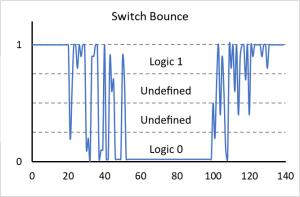 The contacts on mechanical switches vibrate as the switch position is changed. This is called "switch bounce". When we are using switches to provide digital inputs this bounce is undesirable so we need to find ways to suppress it.
NOTE: Better quality switches and buttons usually use a spring activated "microswitch" mechanism; however these are often the worst culprits for generating switch bounce!
Where a faster "bounce free" response is required we can use an optical or magnetic sensor, as described on this page.
Why it happens
 The action of switch contacts closing and opening is a little like the action of a hammer being used on an anvil.
When the switch closes the contacts spring together, and the energy of their movement is dissipated in a few bounces.
As the switch is opened the contacts scrape apart, creating a DIFFERENT kind of electrical noise.
Is it a problem?
Well, it depends on your program. If you are just testing for a button press to start a long duration sequence then it matters not; however if you are counting closures, or generating an interrupt it WILL cause problems.
A useful link for more information on switch bounce and debouncing
Measuring switch bounce
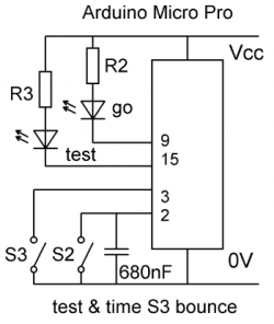 We can use the micros() function on the Arduino to collect data to show how many bounces occur on each transition 0->1 or 1->0 of the switch under test.
My circuit shows a switch being tested - S3, whose condition is indicated by the "test" led (red).
I first used another switch S2 to control the test, and a "go" led (green) to show a test was in progress.
As switch bounce on S2 was causing false readings I used a 680nF capacitor (see below) to very effectively debounce that switch!
The final tests replaced S2 with a button, and repeated tests for 20 changes of the test switch.
You can get the sketch here to try it yourself - results are different for every type of switch.
My results were as follows for four different switches (Switch A, Switch B, Switch C, Switch D):
Switches tested
 Switches A & B are snap action toggle switches;
C a passive push button, and D a "clicky" button.
Despite multiple tests bounce was not detected when using the simple passive push button.
Results of my tests
Switch |
Transition |
Max number of transitions |
Max us to last change |
A |
1->0 |
9 |
776 |
A |
0->1 |
3 |
76 |
B |
1->0 |
11 |
844 |
B |
0->1 |
3 |
104 |
C |
1->0 |
1 |
4 |
C |
0->1 |
1 |
4 |
D |
1->0 |
9 |
1584 |
D |
0->1 |
1 |
4 |
You can see that for these switches, bounce is MUCH greater on closure than on opening. The "mechanism" is different.
Debouncing with a capacitor
Its often recommended to add a small capacitor (typically 100nF) between the digital input pin and ground. This smooths out the effects of the bounce. There seems to be a lot of mis-information about how this works - so here are some results from my experiments.
Data for both of these charts is taken from the worst case values from test runs on switch B.
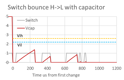
Notice how this works by reference to the diagram & table above. When S2 is activated LOW, without a capacitor there may be a LOT of bounces. With the capacitor in place the closure of the switch discharges the capacitor almost instantaneously through the contact resistance.
This chart and the next show the effect of a 0.022uF capacitor across the switch
If we allow C=0.022uF and Rcontact=0.1 ohm T1=C* Rcontact = 0.002 usec
The capacitor voltage will fall from fully charged 5V to < Vil in 0.002 usec.
When the contacts bounce open C starts to charge via the pullup resistor (30,000 ohm) so the new time constant is T2 = C* Rpullup = 0.66msec
With these values for this switch the bounce open is not long enough for Vcap to exceed Vih.

Here we see the effect of the same capacitor and pull-up resistor on a switch transition from LOW to HIGH with bounce.
Once again when the switch contacts momentarily close the capacitor discharges instantly. When the contacts cease bouncing and remain open the capacitor charges through the pullup resistor and soon the voltage exceeds Vih giving a "logic 1" - as shown here at the 600usec mark.
Adding a small capacitor has another benefit - it keeps the contacts clean. When the capacitor discarges through the switch a large current can flow momentarily, potentially causing a spike; to avoid this we can add a small series resistor as shown below.
Using a capacitor in this way does introduce a small delay.
The time T1/2 to change from 0V to Vih is roughly 0.7CR - so with
C= 0.022uF and Rpullup = 30k T1/2= 460usec
Capacitor debouncing: Words of caution!

Look at Fig 23A. Suppose the switch has been open for some time. The capacitor is charged to Vcc. When the switch S1 closes a current of I = 5V / Rtot flows, where
Rtot = Rs1 +Rcap +Rt
where Rs1 is the switch resistance, Rcap the capacitor resistance, and Rt the resistance of the track connecting them. (NOT a component, just showing the resistance of the track.)
Suppose Rs1 is 0.05 ohm, Rcap=0 (negligible), Rt = 0.05 ohm.
The current is then 5V / 0.1 ohm = 50 Amps.
(In practice the series inductance of the components would dramatically reduce that current)
That will cause a potentially damaging voltage spike (shown !) of -2.5V on other components connected to that track.
By connecting the capacitor DIRECTLY ACTROSS THE SWITCH CONTACT TERMINALS we avoid the current pulse travelling through a track. The current spike still occurs - but has a beneficial effect in keeping the switch contacts clean.
Of course you should choose a suitable small value ( say 0.22uF or less ) so the energy is not too great.
The dissipated energy E = ½ · C · V² for 0.22uF charged to 5V is only 2.5uJ: a tiny amount and not enough to cause heating or damage in most cases, esp. as the loop inductance limits the peak current / power and stretches the pulse.
Debouncing with software
Debouncing with software involves taking frequent readings from the switch to see if it has changed state. Its important to realise that the program does not know what the switch does between readings! The diagram, plots and figures that follow are from simulations in EXCEL, and the values are chosen to illustrate the behaviour of the Bounce2 algorithms. Because Bounce2 uses millis() the time durations need to be much longer than needed for the real life switches I tested.
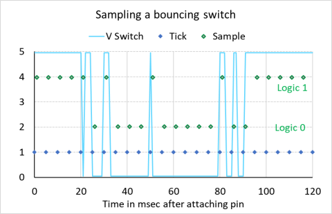
This diagram (left) shows a single switch or button that is checked by a program every 5 msec. The blue dots show the time at which it is checked, and the green dots the result of that check. You can see from the results that the actual time of the first change (H->L or L->H) can be missed depending on the actual time the switch is sampled.
The Arduino "Bounce2" library provides the following functions (and a few more):
void attach(pin number, mode): set up a pin for the switch to use.
void interval(value): set a debounce interval in msec.
bool update(): check the switch state
bool read(); returns the current debounced state
bool rose(): if the state rose 0->1 and
bool fell(): if it fell 1 -> 0
Bounce2 offers three different approaches as follows:
Stable Interval: The default for this library, checks whether the switch value has remained in a stable HIGH (or LOW) state for a period of time "DURATION" (milliseconds).
Bounce Lock-out: following a recognised change prevent response to any further change until a pre-set time ("DURATION") has elapsed
Prompt detection: If the value has been stable for "DURATION" ms a transition is recorded as valid immediately.
If you download and install Bounce2 using Tools/Manage Libraries you can find documentation under /libraries/Bounce2/docs/files/annotated.html
How Bounce2 works
Suppose we call attach() at event 0, and update() every 5msec as shown above, events 1..24.
 We have a switch closure starting at t=20msec, a "transient" at t=50msec, and a noisy switch opening starting at t=80msec
To illustrate the various options I have set "DURATION" at 18msec.
 This graph shows the value reported by Bounce2:read().
Lets start with the "Stable Interval" algorithm. (B2StabInt)
The blue arrows show periods of stability.
At t=25ms (sample 5) the switch value has remained stable from its original value (1) or more than 18ms; However its never stable LOW until sample 15, when bounce2:read() goes low, and we reset the timer.
The switch state remains unstable until at sample 19 it goes and stays high. At sample 23 it has been stable high for 20ms so bounce:read() goes high.
Now the "Prompt detection" algorithm (B2Prompt)
The red arrows show where the signal has PREVIOUSLY been stable.
From the start the switch value has been stable for >18ms so when the switch changes at 25ms bounce2:read() immediately goes low.
The switch value is stable again at samples 11 - 15 - but the "stable value" is again 0, so bounce2:read() continues low.
At sample 16 the low value has been stable for >18ms so the change is immediately recorded on bounce2:read().
Finally, the Bounce Lock-out method. (B2BLO)
The gray arrows show where a new change is "locked out".
The first change is recorded at 25ms - sample 5 - and immediately recorded in bounce2:read(). The timer is reset and no further changes can elicit a response before that timer exceeds 18ms., so the change at 30ms (sample 6) has no effect. However for the spike change at sample 10 the timer is already at 25ms, so bounce2:read() changes to the new value (logic 1) and again the timer is reset. Again no changes can cause a response for at least 18ms has elapsed, when at 95ms sample 19 bounce2:read() goes high.
Conclusions
Each method has its pro's & con's. The stable interval method is sure - but slow to respond. Prompt detection gives a faster response at the expense of responding to transients; while bounce lock out can capture transients and lock out valid changes.
A simpler approach
Another way we can effectively debounce a switch in software is to use a simple digital filter called an Exponential Moving Average. We simply read the switch at regular intervals, and apply this simple formula:
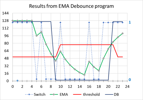
new EMA = 0.25 * switch reading + 0.75 * last EMA. (* NOTE)
So we can use integer arithmetic we start by multiplying the bit from the switch by 128 by shifting left 7 places. The result as you can see is a value of zero or 128, and the EMA lies between these values.
While you can simply get a "1" or "0" by applying a threshold value of say 64, there are circumstances where this would result in sensitivity to interference; so instead we apply some hysteresis with another simple rule:
If (debounced value = 1) threshold = lower; else threshold = upper;
For threshold values I've used 128*0.6 and 128*0.4
NOTE: you can use other factors e.g. 0.2 and 0.8 - as long as they add to 1: 0.25 & 0.75 allow us to use shifts again, for speed of calculation.
Advantages and disadvantages of debouncing with software
In my view any possible advantages of debouncing in software are massively outweighed by the disadvantages.
Debouncing code adds complexity to your program. It adds a requirement to poll the switch at intervals, an unnecessary addition to the load on the computing power. Also I have not seen a published program that takes into account the different characteristics of switch bounce on opening and closing, although the EMA program is easily modified to support this.
Published programs almost exclusively use the millis() function, allowing times of up to 50ms and more to eliminate a bounce. For my tests I needed to use micros(). Why? because on my first attempt using Millis() I NEVER caught a single bounce.
