
Experiments with an Arduino microcontroller
Using an ESP-WROOM-32 Devkit
About the ESP32 DEVKIT
During my development of my NodeMCU 8236 project I soon discovered that while a very powerful and flexible device it was a bit short on hardware I/O. The newer ESP32 DEVKIT sounded interesting so I bought a couple, along with a ST7735S 1.8inch TFT display.
IMPORTANT NOTE: There are many different versions of this board so you WILL need to check that you have the right pin connection layout.
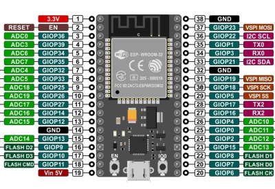
ESP32 WROOM 32 DEVKIT C
 If you need more connectivity or a faster processor the
ESPRESSIF systems ESP32 DEVKIT C
is similar to the Node, sometimes on a slightly smaller board. This board measures 55*28mm overall and has 19 pins each side, (thats 4 more than the NODE) on a 0.1 inch pin spacing with rows 1.0 inch apart. It has no mounting holes.
They are made by several different companies, to slightly different layouts, so you need to find the right pin-out diagram.
Note - the pin-out is different to the NODE's so dont think its a drop-in replacement.
Also as a newer device the support is less well developed, although the technical documentation is actually much better; you can program it with the Arduino IDE, but do check you use the right libraries.
ESP32 WROOM 32 DEVKIT C: Analog input and output
The ESP32 has two 12 bit ADC's ; however ADC2 is used by the WiFi system. ADC1 is multiplexed to 8 channels, attached to GPIOs 32 - 39.
To read an analog voltage you may need to configure the ADC, as you can set different resolution (9,10,11 or 12 bits), conversion rates and voltage ranges (800, 1100, 1350, 2600 mV). The default is 12 bit resolution and 2600mV range.
The ESP32 ADC is very sensitive to noise, very non-linear (+-12 LSB), and has a very substantial dc offset.
Here is my evidence and test results for this assertion
This sketch shows how to configure the ADC, take and average a set of readings, and convert the result to a voltage reading in millivolts.
Sketch to read voltage from ADC
The ESP32 has two 8-bit DAC (digital to analog converter) channels, connected to GPIO25 (Channel 1) and GPIO26 (Channel 2). The output voltage is (N/255) of the 3.3V level.
Technical documentation
Programming the ESP32 DEVKIT
I'm using a portable Arduino IDE to program the ESP32 DEVKIT.
In the IDE, under File - Preferences "Additional Board Manager URLs" enter (or add)
https://dl.espressif.com/dl/package_esp32_index.json
then in Tools - Board - Boards Manager search for ESP32 by Espressif Systems and click "install"
I used the "ESP 32 Dev Module" generic choice and left all options unchanged.
At first the Arduino IDE was not able to program the ESP32- the USB port was not showing
so the board did not appear to be connected. In Windows Device Manager - Ports it was showing a faulty driver "CP2102".
I downloaded the driver from the SiLabs website and after installing the usb port now showed in DevMan, and the IDE was able to program the board..
Note: you need to hold down the "boot" button on the board while uploading a sketch,
or connect a 10uF cap between the EN pin and GND
ESP32 Subtle differences
It ISNT a NODE or an Arduino clone, so dont expect it to be. You access pins via their GPIO number, NOT the pin number. Because they have multiple functions you need to check which you can use*.
This is a good general reference but beware as the DEVKIT3 I'm using has fewer pins than the DEVKIT V1 shown on that page.
* e.g. ADC2 is shared with the WiFi so cant then be used. Also some pins used at start-up so their condition then may be important.