
John Errington's Experiments with an Arduino
Basic voltage measurements with an Arduino.
Lets look at some different approaches.
measuring a voltage within the range of the ADC
measuring a proportion of the supply voltage
measuring an external voltage that is more than the adc reference voltage
measuring other external voltages
1: the simplest case: measuring a voltage within the range of the ADC
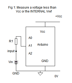
Suppose you are using a UNO and have chosen "DEFAULT" (i.e. Vcc "5V") as your reference.
Provided that Vin is NEVER less than 0V or more then Vcc you CAN just connect your input voltage to an ADC pin - such as A1.
(here the Vin "battery" represents your input signal.)
However if the input happens to exceed those limits the ADC or even the board could be damaged. Its safer to add a "protection resistor" as shown here (R1).
The value should be chosen to limit the current to less than 1mA so for most purposes a 10k resistor will be fine.
(OK unless its connected to the mains or struck by lightning!)
The voltage to be measured is connected between the input point, such as shown here A1, and the Arduino ground.
You may also wish to connect a large value resistor across .input and ground so the input is not left floating if the voltage source is disconnected.
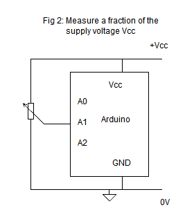
2: measuring a proportion of the supply voltage
Suppose you are using a simple potentiometer type sensor, like you find in a joystick or gamepad. Moving the joystick moves a sliding contact that taps off a fraction Vp of the applied voltage (see diagram).
For best results you should use the "DEFAULT" reference.
analogReference (DEFAULT); // its selected normally anyway, but this makes it clear which we are using

  int potValue = analogRead(A1); // get the value 0 - 1023 into "potValue"
Because we are measuring a fraction of the supply we dont need to worry about exceeding the supply voltage limits - it cant happen.
Suppose the potentiometer is set to 1/4 of its travel.
When the USB supply voltage is exactly 5V
the voltage from the pot. will be
Vpot =
1/4 * 5V = 1.25V
Using the USB supply as reference this gives a reading of
n = 1.25V / 5V * 1024 = 256
If the USB supply falls to 4.40V
the voltage from the pot changes to
Vpot = 1/4 * 4.40 = 1.10V
Using the supply as reference this gives a reading of
n = 1.10V / 4.40V * 1024 = 256.
You can see the value of the supply voltage has no effect on the sensor reading.
3: measuring an external voltage that is more than the adc reference voltage
We can use the same idea of a potentiometer to scale down voltages above the reference voltage so that the Arduino can measure them.
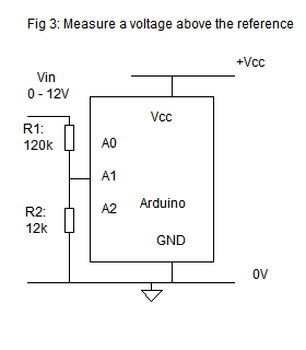
Arduino models using the ATmega168 or ATmega328 have an internal reference of about 1.1V.
This circuit shows how you can use an external resistor divider to scale a 12V input to "about" 1.1V which you can then measure against the internal Vref.
Calculation:
V at A1 = Vin * 12k / (120k + 12k) so
V at A1 = Vin * 0.091 and
if Vin = 12V then V at A1 = 1.091V
Sketch for this circuit
/*
ReadAnalogVoltage
Reads an analog input on analog pin A1, converts it to voltage, adjusts for voltage divider and prints the result to the Serial Monitor.
*/
float sensorValue, vADC, vIn;
float rShunt = 12; //value of resistor from A2 to GND in kohm
float rSeries = 120; //value of series resistor A2 to Vin in kohm
float rFactor; //calculated in setup
float vReference = 1.1; //for ATMEGA 328 boards like the Uno and Nano - check data sheet for others
void setup() {
Serial.begin(115200); // note sensible baud rate
analogReference(INTERNAL); //on the uno & nano this is 1.1V
rFactor = (rSeries + rShunt)/rShunt; //calculate potential divider factor for your resistor chain
}
void loop() {
sensorValue = analogRead(A1); // read the input at the analog pin
vADC = sensorValue * (vReference / 1024.0); //convert it to a voltage
Serial.print("Voltage at ADC is :");
Serial.print(vADC);
vIn = vADC * rFactor;
Serial.print(" Voltage at input is :");
Serial.println(vIn);
delay(1000);
}
4: measuring other external voltages
For positive voltages we use the same circuit as above, but simply change the divider chain. Lets design a circuit to measure in the range 0 - 30V using Vcc as the reference.
The input voltage needs to be below Vcc, so to suit Arduino's with either a 5V or 3.3V Vcc we will choose to keep the input below 3V.
We want a voltage of 0 - 3V at A1, so for a 30V input we will have 3V across R2 and 30 - 3 = 27V across R1. We need a ratio R1:R2 of 27:3, such that R1 // R2 = 10k.
Choosing R2 = 11k and R1 = 100k gives the range we need, with a source resistance of 9.9k
Acknowledgements: All diagrams drawn with MeeSoft Diagram Designer