
John Errington's Experiments with an Arduino
Measure very low voltages with the Arduino:
Arduino millivoltmeter / microvoltmeter using an Instrumentation Amplifier.
For measuring very small voltages we need a more accurate input stage. The best way to do this is to use an instrumentation amplifier circuit as described here. By suitably adjusting the gain you can measure down to microvolts.
Instrumentation amplifier
1: using Op-Amps (see more here)
The circuit provides two measuring inputs V1, V2 that will be used to make a measurement of the voltage difference between them.
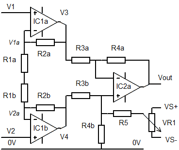 The circuit provides amplification through two stages. First stage amplification is provided by IC1a (IC1b) while the second stage around IC2a amplifies the difference between V3 and V4.
Accuracy depends on the precision of the resistors used, so pairs of resistors Ra, Rb should be matched. However the gain can be adjusted by trimming R1a & b, and any voltage offset by adjusting R5, VR1. (typically R5 = 1000 * R4)
In general amplifiers of this type require positive and negative supply rails connected to each amplifier (indicated but not fully shown in the diagram). A negative supply is easily provided as described below.
The MCP6041/2/4 series are particularly suitable in this application, giving one, two or four op amps in an 8 pin or 14pin DIL package at low cost. (around £2.50 eBay)
2: Using an Integrated Instrumentation Amplifier
As an alternative you could well use the AD623 which combines all these parts in a single 8 pin dip package, and has the advantage of being able to operate from a single supply (but only if V1, V2 fall within the supply range).
3: Using an external ADC
If you need even higher resolution (at the expense of less frequent measurements) the ADS1115 module offers 4 16 bit analog inputs and connects to the arduino via I2C.
Analysis for the Op Amp circuit
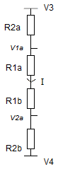
The gain for the first stage (IC1a, IC1b) is easily calculated by considering the current flowing in the resistor chain.
 An ideal operational amplifier is defined as follows:
input resistance infinite; output resistance zero; open circuit gain infinite; bandwidth infinite.
Because of this we can see V1a is equal to V1, and V2a to V2.
I = V3 - V4 / R2a +R1a +R1b + R2b also
I = V1a - V2a / R1a +R1b
The gain (Av1) is Av = V3 - V4 / V1 - V2 = R1a +R1b + R2a + R2b / R1a +R1b
which simplifies to Av1 = 1 + (R2a + R2b / R1a +R1b)
and if R1a = R1b = R1, R2a=R2b = R2
Av1 = 1 + R2 /R1
The second stage, around IC2a, forms a conventional differential amplifier which provides a gain of
Av2 = Vout / ( V4 - V3) = R4 / R3 (once again R4 - R4a = R4b and R3 = R3a = R3b)
Av2 = R4 / R3
Total gain for the Instrumentation amplifier circuit
The overall gain is Av1 * Av2 = (1 + (R2 /R1)) * (R4 / R3)
Typical values
For example if we choose R1 = 10k; R2 = 91k; R3 = 10k and R4 = 1M0;
Then Av = (1 + 91/10)*(1000/10) = 10.1 * 10 = 1010
The gain can now be adjusted to be exactly 100 by reducing the value of R1a + R1b. The easiest way to do this is to connect a suitable large value resistor in parallel with R1a or R1b.
Generating a negative supply for the amplifier
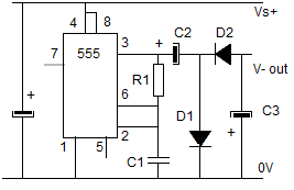 This circuit uses a 555 in an astable configuration giving a 1:1 mark:space ratio. The output is coupled via a capacitor C2 and the waveform rectified through D1 and D2, then smoothed by C3 to give a negative voltage that can provide a negative supply to the op amps.
Typical values
c1: 0.022uF R1: 10k
C2, C3: 10uF D1, D2: IN4048 or similar
Acknowledgements: All diagrams drawn with MeeSoft Diagram Designer