John Errington's tutorial on Power Supply Design
Simple regulated voltage supply
Simplest circuit: RS1
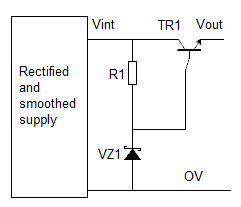
RS1 is the simplest series regulator circuit, using only three additional components;
- a zener diode to give a voltage reference;
- a resistor to feed current to the zener and bias the transistor;
- and a power transistor.
It provides a fixed output voltage of Vz1 - 0.7V
How it works
At switch-on R1 provides current to TR1 and Vout rises. When Vout nears Vz1 - Vbe the base current falls, so output current is reduced to maintain the output voltage at Vout = Vz1 - Vbe
Disadvantages of this simple circuit
- The current to the zener diode is not regulated, so Vref can change
- The base-emitter voltage of the transistor changes with temperature.
- The output resistance is (RZ1//R1)/gain. As HFE is typically 30 for power transistors, and RZ1 about 10 ohms,
Rout is about 0.3 Ohms. The regulation is poor. - The voltage reference circuit uses up to 10% of the available power.
A better circuit: RS2
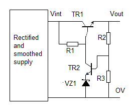 This circuit uses a second transistor to monitor the output voltage. With only three extra components it gives the folowing benefits:
- better voltage regulation, due to negative feedback
- less drift due to constant current through the zener
- programmable (or variable) voltage output
(the output can be made variable by adding a potentiometer in the divider chain of R2+R3 as shown in the example design below)
We use a Darlington pair power transistor for TR1Why a Darlington?
Common power transistors have very low HFE (gain) - typically about 30. An output current of 3A would need a base current of 100mA, causing our regulating components to heat, and the voltage to drift. A darlington pair combines two transistors in one package to give gains of around 1000. Now we can make a 10A supply and only need 10mA in the control circuit.
Further, using a Darlington improves regulation by reducing the output resistance.
As before, Rout = Rint / Hfe.
Rint = the parallel combination of RZ1 and R1. We will show this throughout with a parallel sign //
Just replacing the power transistor in the circuit above with a Darlington changes Rout from
Rout = (RZ1//R1)/gain = 10 / 30 = 0.3 ohms to
Rout = (RZ1//R1)/darlington gain = 10 / 1000 = 0.01 ohms
Also they are inexpensive and keep component count down.
Example design
Design a variable voltage regulated supply to provide 2A at 20V to 30V. We have an unregulated supply that provides (Design Example 1) 38V at 2A, with ripple of 2V peak to peak.
Components:
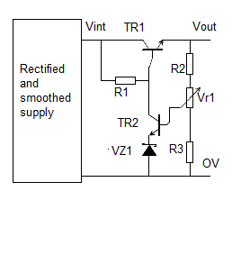

TR1: Power darlington needs to accept 40V and 2A, with a power rating of (40V -20V) * 2A = 40W
This is the popular TIP120, an NPN power darlington with
HFE=>1000; Vceo=60V; Ic=5A; Pd=65W
An Hfe 1000 gives Ib as 2mA when Ie = 2A. We will choose R1 to feeed a minimum of 12mA into TR2 and the Zener.
VZ1: We choose a 7.5V zener (7.5 * 10 = 75mW) type BZX85C7V5 as the tempco of this (+0.2%/K) balances out the tempco of the base-emitter junction.
TR2: needs to take 30-7.5V and 12mA = 250mW The BC546B has:
Collector Emitter Voltage Vceo:65V; DC Collector Current:100mA; Pt=0.6W
DC Current Gain hfe:150
The base current of TR2 is then 10mA / 150 = 66uA. We can ignore the effect of this in calculating the resistor chain.
R1: to determine this we need to know the voltages at Vint and the base of TR1.
Vint (max ) = 38V + 2V = 40V; Vint(min) = 38 - 2 = 36V
Vb1 (max) = 30 + 0.7 = 31V; Vb1 (min) = 20 + 0.7 = 21V
VR1(max) = (Vint (max ) - Vb1 (min)) = 19V; VR1(min)= (Vint(min) - Vb1 (max)) = 36 - 31 = 5V.
The current IR1(max) = VR1(max) / R1 and IR1(min) = VR1(min)/R1 - so
IR1(max) / IR1(min) = VR1(max) / VR1(min). This is a variation of 4:1.
IR1(min) needs to be > Ib for TR1 which was 2mA, and also allow for correct bias current for the zener.
The 7.5V zener wants around 10mA to achieve low Rz.
So let IR1(min) be 8mA + 2mA = 10mA.
R1 = 5/10 = 0.50 k - nearest = 0.470 then Imax = 10/0.470 = 21mA. R1 = 470 ohms.
21mA * 19V = 0.40mW. We need a 1W or better resistor.
Calculate the divider chain
R2, R3, VR1. To calculate these we start by assuming R3=1kohm.
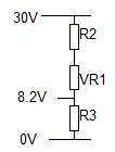 This diagram shows VR1 slider at the bottom of its track.
Rtotal = R2 +VR1 +R3; IR2 = IVR1 = IR3;
IR3 = 8.2V /( R3 = 1k) = 8.2mA;
30V = Rtotal * 8.2mA so Rtotal = 30/8.2 = 3.66k
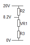 In this configuration the slider is at the top of VR1.
I= 20V / Rtotal = 20 / 3.66 = 5.46mA
(R3 =1k) +VR1 = 8.2V / 5.46mA = 1.5 kohm. so VR1 = 0.5kohm.
R2 = 20V - 8.2V / 5.46mA = 11.8/5.46 = 2.16kohm
Check; 2.16k + 0.5k + 1k = 3.66k
We need to make VR1 a preferred value for a potentiometer. We could choose 1k; this would give a maximum divider chain current of 8.2 / 2 = 4.1mA - which is fine. We simply scale all the values.
R3 = 1k0*2 = 2k0; VR1 = 0.5k * 2 = 1k0; R2 = 2.16k * 2 = 4.32k
Where suitable resistor values are not available we can make them up by adding resistors in series.
So we would use 2*1k resistors to make R3; R2 would be 3.9k + 430 ohm.
