John Errington's tutorial on Power Supply Design
Smoothing
We saw that the output from the transformer and rectifier was a DC voltage; but it contains a large unwanted AC component.

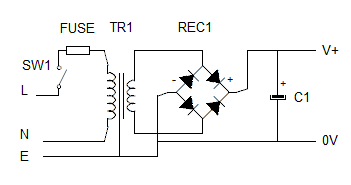
We can reduce this AC component by adding a capacitor, as shown here. The effect of this is
- to increase the average output voltage, and
- to provide current when the output voltage drops.
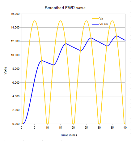
This is shown in the graph below. Note also the addition of a switch and fuse in the live rail.
As before all calculated figures apply to a 12V RMS voltage from the transformer.
For our calculations we will choose a 10mF (10,000uF) capacitor, and assume a load of 6 ohms,
a transformer internal resistance of 0.5 ohms, and a rectifier voltage drop of 2V.

The yellow line shows the output voltage from the previous unsmoothed supply with a 2A load
We saw in the previous page that the rms value of our "dc" wave is roughly 10.6V
Lets see how adding the capacitor changes this.
The highest output voltage has fallen a bit; but the lowest output voltage has gone from 0V to 11.6
This means the RMS value of the output wave is now much higher.
NB: Adding a smoothing capacitor increases the average output voltage.
Ripple voltage calculation
The size of our ripple wave shown above is 1.3V pk-pk and its "almost" a sawtooth wave. The rms value for a sawtooth wave is Vrms = Vpp / 2*sqrt(3) = Vpp / 3.46
Here Vpp ripple is 1.3V so Vrms for the ac wave is 1.3 / 3.46V = 0.375V (unsmoothed value was 5.4V)
The RMS value of the output waveform is 12.0 V. This is higher than the 10.6V for the unsmoothed supply.
Capacitor calculation
 The amount of ripple voltage is given (approximately *) by
Vpk-pk ripple= Iload /4 f C (see below) where
f is the frequency before rectification (here 50Hz) and
C is the value of the capacitor.
Example: for our 12V supply we require a ripple voltage of less than 1V peak - peak, with a 2A load.
Rearranging Vpk-pk ripple = Iload / fC we get C = Iload / 4 * f * Vpk-pk ripple
C = 2A /4* 50Hz * 1V whence C = 2 / 200 Farads = 10,000 uF
(* in fact the voltage ripple also depends on the internal resistance of the transformer and rectifier. More resistance gives better smoothing but worse load regulation)
Why Vpk-pk ripple= Iload /4 f C?
In each half cycle the output voltage rises and falls. The discharge time t between each peak and trough is then roughly half of each half cycle - or one quarter of the period T of the unrectified wave.
We use Q (charge) = C V = I t , and rearrange to get V = I t / C so V = I T / 4 C.
T = 1 / f , Whence V = I / 4 f C
Voltage calculation
The minimum output voltage is Vout = Vpk - (Vpk-pk ripple)
In the above example Vpk = 14.6V and Vpk-pk ripple= 1.3V so Vout (min) = 13.3 V
Ripple current
The storage and release of charge in the capacitor results in an AC current flowing through it. This causes heating of the capacitor and can be destructive. On the next page we evaluate the size of this current.
Worked Example
Design a mains operated power supply to the following specifications: Output voltage 24V ± 20 % at 5A with maximum ripple voltage of 4V peak-peak.
We will need:
- a suitable transformer, rated at 5A continuous
- a bridge rectifier capable of passing a peak current of 2*5A continuous,
with a reverse voltage rating greater than 3 * Vrms (or 2 * Vpk) - a smoothing capacitor
Calculations:
1: Choose rectifier: our chosen rectifier data sheet says it has a forward voltage drop of 2.7V at 5A
2: work out needed voltage: Vrms * 1.414 must be > 24 + 2.7 + (Vripple = 4V)=30.7; Vrms = 30.7/1.414 = 22V.
3: choose transformer: The nearest suitable transformer is 24V at 8A - that will be fine.
4: choose capacitor: remember Vpk-pk ripple= Iload /4 f C - or C = Iload /4 f * Vpk-pk ripple
C = 5 / 4* 50 * 4V = 5 / 800 = 0.00625 = 6,250 uF
with a minimum voltage rating of 24 * sqrt(2) = 34V + 20% safety margin = 40V
