John Errington's tutorial on Power Supply Design
Voltage regulation
For many purposes a correctly designed simple rectified and smoothed supply will suffice. However many applications require a more accurately controlled output. The following pages explore the design of power supplies with increasingly demanding regulation of voltage output.
All are based on the simple supply already dicussed. The basic design is a "Series regulator" and is the same for each of my designs, as shown in this block diagram.
(see below for the alternative -less efficient - shunt regulation)
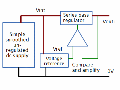
The output from the uregulated supply provides power for a voltage reference. The output from this is compared with the output voltage Vout+.
If Vout>Vref a signal is applied to the series regulator to reduce Vout. If Vout<Vref a signal is applied to the series regulator to increase Vout. In this way Vout is maintained at a value close to Vref.
Series regulated supplies always require a higher voltage at the input to the regulator, which is then reduced to give the required output. This is called "drop out". Because of this the series regulator consumes power equal to (Vint - Vout ) * Iout, and so the regulator must be designed to cope with the heat produced.
Load regulation of unregulated supply
Remember for our unregulated supply the voltage falls and ripple rises as the load is incresed. Your design must ensure there is a "safety margin" of excess voltage to allow for this.
Vint(max load) - Vpk ripple(max load) - Vdrop out > Vout
Performance of Series regulator
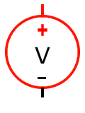
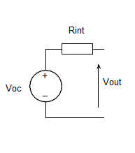 Any power supply can be described in terms of its Thevenin Equivalent Circuit.
Voc is the open circuit voltage; Vout the output voltage when current is supplied to a load; and Rint the Thevenin Equivalent resistancce - the output resistance of our supply.
Remember load regulation Reg = (Voc - Vrated) / Vrated
Voc = Vrated + Irated * Rint
Reg = (Vrated + Irated * Rint - Vrated) / Vrated = Irated * Rint / Vrated
So for good regulation we need Rint to be as low as possible.
Shunt regulation
Sometimes series pass regulation is not appropriate, (eg with extremely high resistance loads) and in this case a shunt regulator may be used. Although less efficient than the series regulator, it is, however, simpler. This form is very common for voltage reference circuits.
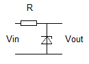 In the absence of a load the current that flows in the circuit is
I = Vin - Vout / R
when a load is connected the current through the shunt regulator (shown here as a zener diode) falls. As load current increases the current through the regulator falls. Regulation is maintained until the current through the regulator falls to zero, after which the output voltage Vout will fall.
Shunt regulators work very well provided the load is small, constant and well-behaved.