John Errington's tutorial on Power Supply Design
Voltage references
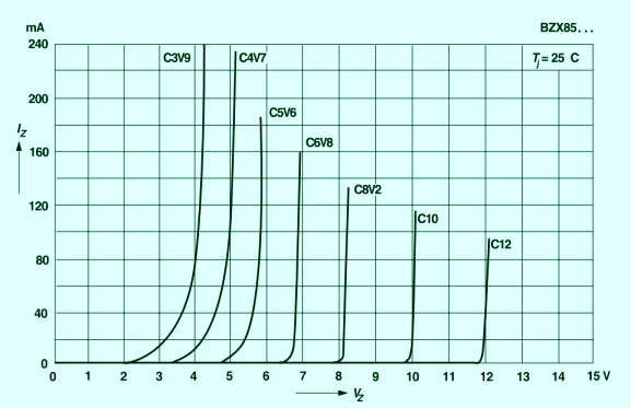
The accuracy and stability of the finished supply is dependent on the accuracy of the voltage reference. The most common voltage refernce used in power supplies is the zener diode. Below you can see the voltage/current characteristic for the BZX85 series of zener diodes.
 You can see the 10V "Zener" has a steeper slope and sharper knee than the 3.9V "Zener"
Thats because the way they work is different. At low voltages the reverse breakdown is due to the Zener effect.
At around 5V the Avalanche effect starts to become significant and at high voltages its the most important element.
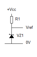
 This is how a zener diode is used to provide a voltage reference. R1 is chosen to give the desired current through VZ1, avoiding the lower current where the knee is important, but also keeping the total power well below the dissipation of the device.
Example: Vcc = 20V with 3V ripple. Vref = 12V.
We choose a BZX85c12 which is rated 1.3 watts.
Choose I = 30mA so the total power dissipation in the zener is Pt = 12 * 30 = 360mW.
R1 = Vcc - Vz1 / I
R1= 8 V / 30mA = 270 ohms
At this current the 12V zener has a slope resistance of around 10 ohms. (data sheet)
When Vint is 20 +3V then I = 23 - 12 = 11V / 270 ohms = 40.7mA (and Pt is around 12*40 = 480mW)
When
Vint is 20 - 3V then I = 17 - 12 = 5V/270 ohms= 19.5mA
This current variation will cause a variation in Vz of 40 - 20 = 20mA * 10 ohms = 200mV. However if the current chosen was too low, Vcc too close to Vz, or a current drain caused Vint to fall, then a larger change in Vz would result.
Similarly, if a current is drawn from the circuit that also would cause the zener current to change, and thus the output voltage. For best results as a voltage reference we need to operate the zener at constant current. See page on current sources.
Alternative voltage references
While carefully chosen zener diodes are capable of providing good voltage references, their output voltage does change with current and also with temperature. For more demanding applications temperature compensated voltage references are available. These use a forward biased silicon diode whose temperature coefficient ranges from –2.1 to –2.3 mV/K and a 7.5V zener (tempco around +2mV/K) to give an 8.2V reference.
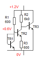
 If a low voltage reference, or a particular voltage, is needed a "bandgap reference" may be used. Based on the design shown here by RJ Widlar, modern bandgap references are available in a wide range of voltages. As an example the popular and inexpensive MAX6100-MAX6107 range are low-cost, low-dropout (LDO), micropower voltage references. These three-terminal references are available with output voltage options of 1.25V, 1.8V, 2.048V, 2.5V, 3V, 4.096V, 4.5V and 5V. They feature a low temperature coefficient of 75ppm/°C (max) and an initial accuracy of ±0.4% (max).
For extreme accuracy (up to 6 figures!) a "buried zener" technique is used, with a temperature stabilized enclosure.
Voltage reference IC's come in two main types - a "shunt reference" that is used just like a zener diode;
and a "series reference" that is used like a common regulator IC.
For more information on choosing the right voltage reference Linear do a great document here.
