John Errington's tutorial on Power Supply Design
Constant Current and Current limiting
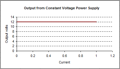
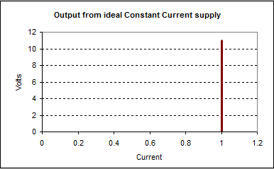
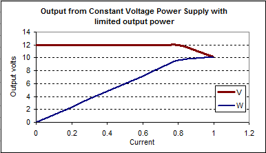
Often we may just wish to protect the components of a constant voltage supply from damage if too great a load is applied. However we may require a power supply that will provide a constant current into a load. One such application is in electroplating.
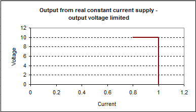
No supply can produce an ideal constant current. As the load on the supply is reduced the voltage rises to maintain the set current. Eventually we must reach a point where the supply is no longer able to do so.
 |
 |
 |
 |
To provide a constant current we need to sense the output current, compare with a set value, and use this to control a regulating element. Here is one way to add a constant current (or current limit) to our simple regulated supply.
Simple current limit circuit
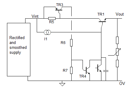
In normal operation current flows to the load through TR1. Resistor R5 (typically around 0.1 ohm) is used to sense this current. When the voltage across R1 exceeds 0.7V Tr3 starts to conduct, turning on TR4 and depriving TR1 of base current. The load current then stabilises at the point where TR3 just starts to conduct. (ie VR5 = 0.65V approx).
If R5 = 0.05 ohm the output current will be limited to
Imax = 0.65V/0.1 ohm = 6.5A
A variable current limit can be arranged by placing a potentiometer (eg 1k) across R5 and tapping off the required voltage.
Precise variable constant current
Our "precise voltage supply" can similarly be adapted to give a constant current or current limit facility, as shown here.
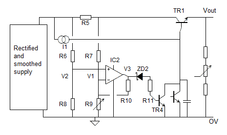 As before R5 senses the current drawn. Resistors R6, R7, R8, R9 form a wheatstone bridge arrangement. Values are chosen so that the voltage limits for the IC are not exceeded. Lets suppose we choose
R6 = R7 = 47k and
R8 = R9 = 4.7k
IC2 measures the difference in voltages V2-V1 and amplifies it.
As before TR4 robs TR1 of base current to maintain Iout at the set value.
R9 is adjusted to allow the required current to flow.
Limitations of this circuit
As with any constant current supply as the load resistance increases we will eventually reach a point where the supply can no longer provide enough voltage to drive the set current through the load. Within these limits the circuit will perform extremely well.
Sensing the output current
Iout = Ie = Ib + Ic
We cannot sense emitter current without increasing the output resistance when used as a voltage supply. However by using a darlington arrangement the base current is typically less than 0.1% of emitter current so Ic is a good measurement of Ie.
As with the previous circuit this arrangement can be easily adapted to provide large output voltages.
(see High voltages)
