
John Errington's Experiments with an Arduino
Voltage measurement with the Arduino
The examples already described allow reasonably accurate measurements to be made - but only if the source has a very low internal resistance. Most voltmeters are made to have a high impedance so that they do not significantly change the voltage being measured.
If you are unsure about "op amps" and how to use them you will find more explanation
on the "Operational Amplifiers" page.
Effect of voltmeter impedance on accuracy of measurement
The diagram shows a voltage source (i.e. whatever you are measuring the voltage of) connected to your measuring device (voltmeter).
Lets look at what happens when we make a measurement with our arduino.
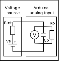 The Arduino chip analog input circuit has an impedance of
more than 1Gohm //14pf. (Shown here Rp, Cp) Also the analog input pins can show a leakage current of 1uA (but typically 50nA).
These can reduce the accuracy of our measurements if the source resistance Rint is high, especially as the sample time window only allows about 6us for the 14pf capacitance to charge.
This is why the arduino spec recommends a source resistance of <10k.
The measurement error due to charging is Vo / Vs = (1-exp( -t / R C);
putting t = 6ns, C = 14pf, Rint = 10k we get t / R C = 6/140 = 7; and
Vo/Vs =(1-exp(-7) = 1 - 0.000912 which gives an error just less than 1LSB.
What happens if the source resistance is high?
I've done tests using a 500M source resistance. FOr a stable input voltage the readings were unchanged. So an analog input has all the input characteristics of a very good voltmeter.
How can we provide a low source resistance?
For voltages between 0 and 5V we can use an Operational Amplifier (see below) in a voltage follower configuration as shown here. Vin is the voltage you are measuring, and Vout connects to the analog input on the Arduino.
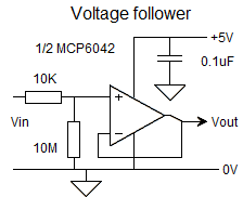 Normally we would use positive and negative supplies to power an Op Amp; however modern CMOS Op Amps are able to accept inputs and provide outputs through the whole supply range. This simple configuration, with only four components, will give an input resistance of ten megohms, a VERY low output resistance, and will also provide protection against static and overvoltage or reverse voltage at the input.
The MCP6041/2/4 series are particularly suitable in this application, giving one, two or four op amps in an 8 pin or 14pin DIL package at low cost. (around £2.50 eBay)
If Vin will always be connected to a source you can even omit the 10M resistor!
measuring other external voltages
For positive voltages we use the same circuit as above, but simply change the divider chain. Lets design a circuit to measure in the range 0 - 20V.
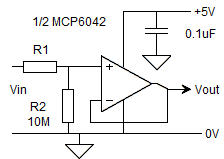 The divider needs to present a voltage Vout of 0 - 5V at A0, so for a 20V input we will have 5V across R2 and 20 - 5 = 15V across R1.
Choosing R2 = 10M and R1 = 30M gives the range we need. You can chain three 10M resistors to make the 30M resistor. Alterrnatively you could use a 3M3 resistor for R2 and a 10M resistor for R1.
Again Vin is the voltage you are measuring, and Vout connects to the analog input on the Arduino.
measuring negative voltages
For negative voltages we use an inverting amplifier. Lets design a circuit to measure in the range 0 to -5V .

Choosing R2 = 1M and R1 = 1M gives the range we need.
The MCP6042 is again suitable as the output can swing from the 0V to the 5V rails. It needs no negative supply.
The diagram shows an additional input from a reference voltage so if we wish we can calibrate against that; alternatively if less accuracy is required you can just use the internal reference.
This circuit will need you to use an op amp that is happy with inputs at the same potential as the negative (ground) supply.
An alternative is to connect the non-inverting input to a source of a small positive voltage; and you will then need to calculate your voltage measurement from the ADC or apply a simple calibration.
For all the above examples its necessary to calibrate the measurement system.
If you are new to using operational amplifiers, see the next page Operational amplifiers for your Arduino projects
Acknowledgements: All diagrams drawn with MeeSoft Diagram Designer