
John Errington's Experiments with an Arduino
How the Arduino ADC measures an input voltage
NOTE: The information on this page refers to the ADC found embedded in modules based on the ATMEGA 168, 328 and 32U4, and also the Espressif ESP8266. "Arduino" boards using other devices - particularly the Espressif ESP32 will have different specifications and characteristics.
The system on an Arduino chip that measures an input voltage is a "Successive Approximation Analog to Digital Converter".
Convert your reading to a voltage
How it works
Here is a block diagram showing the important parts:

The first step is that the applied voltage Vin is "locked" by the Sample and Hold circuit. (As the conversion process proper has not yet started I've called this clock cycle zero.)
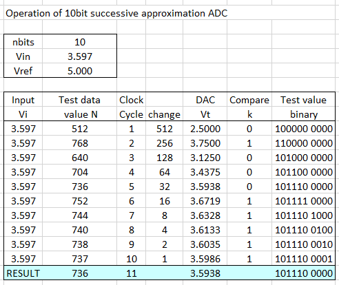
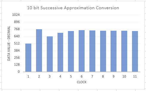
After that the Successive Approximation register and control logic (SAR) applies a series of ten "test value" numbers to the DAC.
The corresponding voltage Vt is compared with the "locked" signal, Vi, by the comparator. This returns a logic signal K to the SAR as follows: If Vt > Vi k=1; else k=0.
If the voltage Vt generated by the DAC is bigger than Vi the test value is removed and a smaller value tried. Otherwise the test value is left and a another test value added. The process can be seen in the chart below.
When the last test value has been applied the comparator output is used to apply any final correction to the data value. Then on the last clock cycle (now 13 in all) the result is recorded and conversion is complete.
In effect we have divided the input voltage range into a series of steps. The smallest change we can measure is between one step and the next. In all there are 1024 steps, corresponding to values N of 0 to 1023, so the height q of each step is q=Vref/1024.
If you would like to try different values you can download the excel spreadsheet I used.
Converting a measurement from a number to a voltage
The result from our measurement above shows a reading of 736 or 0B10 1110 0000 for an input of 3.597V.
To convert this to a voltage reading we need to multiply the reading by the size of step (q).
So Vmeasured = N * Vref / 1024
and for our reading of 736 Vmeasured= 736 * 5.000 / 1024 = 3.5938 Volts
CORRECTION
To be strictly accurate our reading lies in the band between 736 * 5.000 / 1024 and 737 * 5.000 / 1024 volts, so we can add a very small correction factor like this
Vmeasured = (N + 0.5) * Vref / 1024
so our reading of 736 gives Vmeasured= 736.5 * 5.000 / 1024 = 3.5962 Volts
CAUTION
We can only be certain of measurements that do not exceed the range of the ADC. If we apply a voltage of a little more than 5V to the ADC it will do no harm - but the result will not be correct. So we can not legitimately convert a reading of 1023 to a voltage.
Its also true that a small negative voltage will not be correctly measured, but usually the circuit does not allow voltages of less than zero at the input.
Also, the above assumes that you are computing the voltage as measured from a voltage reference. If you are using a calibrated value you will need to use those values, as shown in the "calibration" page.
1023 or 1024?
There has been a LOT of argument over whether the correct conversion for a 10 bit ADC is
Vmeasured = N * Vref / 1024 - or - Vmeasured = N * Vref / 1023
Lets look at a 2 bit ADC with a Vref of 5V and range of 0 to +5V; the range is divided into 2^2 = four equal "domains" or "bins". The input Vin can be any value in the range 0 - 5V and all are equally likely.
The diagram shows the numbers and voltages for such an ADC. Shown in blue are the median voltages for each value
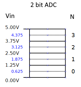
If you apply a voltage of between 3.75 and 5.00 Volts the output will be a "3". N=3
1: Lets try Vmeasured = N * Vref / (2^n) -1
so Vmeasured = 3 * Vref / 3 = 5.0V
and if N=0 Vmeasured = 0 * Vref / 3 = 0.0V
2: Lets try Vmeasured = N * Vref / 2^n
so Vmeasured = 3 * Vref / 4 = 3.75V
and if N=0 Vmeasured = 0 * Vref / 4 = 0.0V
The "best" conversion is one that gives as a result the median voltage within the "bin" - ie 4.375 for N=3
3: Vmeasured = (N + 0.5) * Vref / 2^n whence Vmeasured = (3 + 0.5) * 5.0 / 4 = 4.375V
Some people see as a problem that this does NOT give zero when the input voltage is zero. But zero is NOT the most representative value for that range; for this converter the most representative value is 0.625 volts.
Better or faster readings
You can get higher precision in your readings by averaging as described here
Clock Prescaler
Its possible by choosing a different clock prescaler to perform conversions more quickly; however because the circuit - particularly the comparator - takes time to settle FASTER READINGS WILL BE LESS ACCURATE.
External Analog to Digital converters
The ADS1115 module offers 4 16 bit analog inputs and connects to the arduino via I2C. However the ADC is not a successive approximation type, but a Sigma-Delta converter.
This achieves high resolution (lots of bits) - but often at the expense of much slower conversion rates.
Further reading
Nick Gammon's page has lots more very useful information.