
John Errington's Experiments with an Arduino
Voltage measurement with the Arduino board: Calibration
Why do we need to calibrate our voltmeter?
The ADC will give you a reading; its just a number. Converting that to a voltage reading will depend on the following:
- The Arduino you are using, and its ADC
- The voltage reference you have chosen and
- The external circuit.
To make things simple lets assume you are using a Uno to measure a voltage on an analog input, using the INTERNAL reference
Circuit for simple calibration
Calibration with an external circuit
Offset Error

Usually the ADC will not read the true voltage for very small values.
This is "Offset Error" as shown here.
Offset error is inherent in the ADC
To get sensible readings for voltages near zero we need to adjust for that, by adding a small value to the adc reading before doing the conversion to voltage.
To give an example my Uno has an offset error of 3mV, so a 4mV input reads 1mV.
These graphs are adapted fom the ATmega data sheet DS40002061B for the 328 and similar devices.
Gain Error

The usual source of a gain error is by using an inexact value for the voltage reference.
INTERNAL: a built-in reference, equal to
about 1.1 volts on the ATmega168 or ATmega328;
also on the ESP32; and
about 2.56 volts on the ATmega8 and 32U4 chip boards.
We can correct for gain error by providing a more accurate value for the reference voltage, using two point calibration as described here.
To give an example the INTERNAL reference on my UNO is actually
1085 mV, not 1100 mV
These graphs are adapted fom the ATmega data sheet DS40002061B for the 328 and similar devices.
Calibration circuit
To do this we need to "calibrate" the ADC by applying
- a known small voltage - to A0 to find the correction needed for offset error; (as shown in the figure)
THEN - a known voltage in the upper range of the ADC to A0 - so if using the "1.1V" "INTERNAL" reference we need about 1.0V
So move the link (blue) and voltmmeter to the 990mV point.
This is called "two point calibration" and is only suitable for a reasonably linear ADC as found on most chips - with the exception of the ESP32.
The schematic here shows how you can do this with a simple voltage divider from the 3.3V output. The resistor values shown will give ABOUT the right voltages, but for accurate calibration you need to measure them with a meter.


If using a board that has a "2.56V" reference you would need a divider chain of 3V3 - 1k0 - 2k2 - 33ohm - GND to give about
2280mV to A0 and 34mV to A1
For calibration you would need to measure these voltages, then insert them via the serial monitor when requested by the program that follows.
Calibration code
Here is the code used to perform the calibration - it looks complicated, but its mostly prints so you can see what is going on.
/*
Program to perform two point calibration for an ADC input
Reads analog input, prints the raw values and calculated results to the Serial Monitor.
Determines and adjusts for offset and gain error
Note you need to insert some appropriate values into the constants for the program - marked ***
The circuit:
- potential divider from +3.3 to give about 980mV to A0 and 32mV to A1
voltmeter to read the exact value on A0
https://skillbank.co.uk/arduino/calibrate.htm
*/
// Characteristics of ADC - insert values for the ADC range on chip you are using: These are for the UNO
int adcRange = 1100; // *** in millivolts, for UNO or other 328 based board, using the INTERNAL reference
//int adcRange = 2560; // *** in millivolts, for micro or other 32U4 based board, using the INTERNAL reference
int adcNBits = 10; // *** enter the number of bits for your ADC - eg A UNO micro etc has 10 bits
int offset = 0; // to adjust the offset error - set to zero initially and corrected during calibration
int vScale = adcRange; // to adjust the voltage scale - initially set to the expected value of the voltage reference
float adcBits; // adcBits = 2^10 = 1024
float adcResolutionmV;
float a0Value; // raw value read from Analog pin A0
float a0mVolts; // reading from Analog pin A0 converted to millivolts
//actual voltage levels for calibration
int vLow; // Enter your measured low voltage in mV when requested via serial monitor
int vHigh; // Enter your measured high level voltage in mV when requested via serial monitor
void printADCchars(); //print out the characteristics of the ADC
int calcOffset(); // read the low voltage input and evaluate the necessary offset value
int calcScale(int initVal); // read the high voltage input and evaluate the necessary scale value
float readADC(int adc, int n); //take and average n values to reduce noise
void setup() {
Serial.begin(57600); // initialize serial communications at 57600 bps:
while (!Serial) { ; } // wait for serial port to connect. Needed for native USB
printADCchars();
pinMode(A0, INPUT);
analogReference(INTERNAL);
a0Value = analogRead(A0); //dummy read
//calculate and adjust offset and scale
offset = calcOffset();
vScale = calcScale(vScale);
Serial.print("The correct values for your programs on this device for future use are: offset: ");
Serial.print(offset);
Serial.print(" and vScale: ");
Serial.println(vScale);
Serial.println("Readings below are now corrected for offset and gain error \n");
}
void loop() {
// read the analog value and display raw reading and voltage in mV
a0Value = readADC(A0, 16);
a0mVolts = ((a0Value + offset) * vScale) / adcBits; // convert reading from Analog pin A0 to true voltage in millivolts
// print the results to the Serial Monitor:
Serial.print("A0 reading: ");
Serial.print(a0Value,0); //raw analog reading: dont show figures after decimal point
Serial.print(" A0 mV: ");
Serial.print(a0mVolts,0); //voltage in mV: dont show figures after decimal point
Serial.println();
delay(5000);
}
void printADCchars() {
Serial.println();
adcBits = pow(2, adcNBits);
adcResolutionmV = adcRange / adcBits;
char adcResStr[10];
dtostrf(adcResolutionmV,5,2,adcResStr);// prepare floating point value for printing in a 5 character field with 2dp precision
char ADCchars[150]; //buffer for sprintf
sprintf(ADCchars,"ADC Nbits = %d so ADC bits = %d: ADC range is %d and ADC Resolution = %s mV",adcNBits,int(adcBits),adcRange,adcResStr);
Serial.println(ADCchars);
}
float readADC(int adc, int n) { //take and average n values to reduce noise; return average
float reading = analogRead(adc); //dummy read
reading = 0;
for (int i = 0; i < n; i++) {
reading += analogRead(adc);
}
float average = reading / n;
return (average);
}
int calcOffset() {// read the low voltage input and evaluate the necessary offset value
Serial.println("Connect low voltage to input then enter its value in millivolts:");
while (Serial.available() == 0) { // wait for input
}
vLow = Serial.parseInt(); // read the incoming integer
Serial.print("Low input voltage in mV is: ");
Serial.println(vLow);
//calculate error and adjust offset value
a0Value = readADC(A0, 16);
a0mVolts = (a0Value * vScale) / adcBits; // reading from Analog pin A0 in millivolts
float difference = vLow - a0mVolts; //error in mV
int newOffset = round(difference); //the offset is in ADC bits, not mV
Serial.print("low reading: ");
Serial.print(a0Value);
Serial.print(" A0 mV: ");
Serial.print(a0mVolts);
Serial.print(" Offset error mV is : ");
Serial.println(difference);
Serial.print(" new offset value is : ");
Serial.println(newOffset);
return (newOffset);
}
int calcScale(int initVal) { //read the higher voltage input in mV and evaluate the necessary scale value
float vError; // voltage reading error for vHigh - mV
float vDifference; // reading error at full scale -mV
float nDifference; // full scale error in bits
int newScale; //the corrected scale value
Serial.println("Connect higher voltage to input then enter its value in millivolts:");
while (Serial.available() == 0) { // wait for input
}
vHigh = Serial.parseInt(); // read the incoming integer
Serial.print("High level voltage in mV: ");
Serial.println(vHigh);
// read the high voltage input and evaluate the necessary scale value
a0Value = readADC(A0, 16);
a0mVolts = ((a0Value + offset) * vScale) / adcBits; // reading from Analog pin A0 in millivolts
Serial.print("high reading: ");
Serial.print(a0Value);
Serial.print(" A0 mV: ");
Serial.print(a0mVolts);
vError = vHigh - a0mVolts; //error in reading vHigh - in mV
vDifference = vError * (adcBits / a0Value); //error at full scale in mV
nDifference = round(vDifference / adcResolutionmV); //error at full scale in bits
Serial.print(" Scale error mV is : ");
Serial.println(vDifference);
newScale = initVal + nDifference;
Serial.print(" new scale value is : ");
Serial.println(newScale);
return (newScale);
}
The output will look something like this:
ADC Nbits = 10 so ADC bits = 1024.00 : ADC range is 1100 and ADC Resolution = 1.07 mV
A0 reading: 25.94 A0 mV: 27.86 Offset error mV is : 3.14
new offset value is : 3
A1 reading: 918.63 A1 mV: 990.03 Scale error mV is : -15.64
new scale value is : 1085
*** readings are now corrected for offset and gain error
A0 reading: 918 1 mV: 976
External circuit
The gain error - and to some extent the offset error - will be affected by any external circuit; so if you have an external circuit - such as this - you should perform the calibration on the whole system. The process is the same.

At the INPUT (here the top of R1) apply a KNOWN (measured) LOW voltage to perform the offset correction.
Then apply a KNOWN (measured) HIGH voltage - withinin the upper part of the measurement range.
So taking this example you could use a simple potentiometer to
- apply a voltage of around 0.1V for the offset error correction, then
- apply a voltage of about 11V for the gain error correction
and insert the appropriate measurements into the program above.
External circuit errors
Common resistors are sold in "preferred values" chosen to cover the normal range of requirements. For example the E12 range (of 10% tolerance) has 12 values in each decade, as follows:
10R, 12R, 15R, 18R, 22R, 27R, 33R, 39R, 47R, 56R, 68R, 82R ; then their multiples 100R, 120R etc.
So a "47k" E12 resistor will have a tolerance of 10% or +- 4.7k
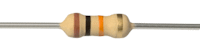
For best accuracy we can use higher spec (more expensive) resistors. The tolerance is shown by the color of the rightmost band as shown below.
E12: 10% tolerance (silver); E24: 5% tolerance (gold); E48: 2% tolerance(red); E96: 1% tolerance (brown)
Dont worry if you dont have precise resistors, the calibration process will correct for those errors.