
Experiments with an Arduino: keypress simulator (cont)
Keypress simulation using the Arduino Pro Micro
For my first sequence I'll generate a..z; A..Z and Symbols/numbers.
Other sequences could for example open Notepad, or a command window to execute common tasks.
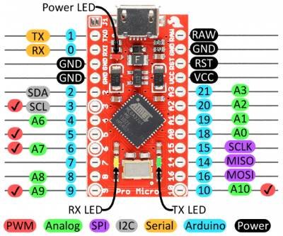
Pin assignments:
We need to start by looking at pin assignments. I'm going to use a hardware interrupt, and one pin for output to operate an LED.
I'll use other pins to add a 6 way switch to choose from a small range of key sequences; and a potentiometer connected to an analog input to set the speed at which keystrokes are entered.
Taking committed pins first I will need the following:
I2C interface to LCD display - so pins 2 and 3 are then unavailable;
Serial interface for testing - so external pins 0 and 1 are unavailable;
One external hardware interrupt: On the pro micro there are 5 pins that can generate a hardware interrupt, as follows:
Pin 0 - INT2; Pin 1 - INT3; Pin 2 - INT1; Pin 3 - INT0; as these pins are already spoken for we use the last
Pin 7 - INT4
Now we need a digital output, an analog input, and some digital input pins to connect to our selector switch.

Final pin assignment
Pins 0, 1: not connected - reserved for serial I/O;
pins 2, 3: I2C to communicate with 16*2 LCD display;
Pin D7: push button for hardware interrupt.
pin 9: LED indicator;
pin 10 = A10: Analog in from rate potentiometer;
A1, A2, A3
= PF6, PF5, PF4
used as digital inputs connected to selector switch S2.
A8 measures Vusb via a potential divider 33k:10k R4 R3
The Vcc ("5V") comes directly from the USB port with no intervening components except for a fuse.
I've also during testing added a switch (S3, not shown) to reset the arduino.
Switch coding
The diagram shows the switch in position 4. In this position A1 is pulled down via D1 and S1:4 and A3 through D3 and S1:4.
This generates a code of 0b1010XXXX on PortF.
The table below gives a full list of generated codes.
Switch position |
A0..A3 |
PF7..PF4 |
!(PF7...PF4) |
code |
0 |
1 1 1 1 |
1 1 1 1 |
0 0 0 0 |
0 |
1 |
1 1 1 0 |
1 1 1 0 |
0 0 0 1 |
1 |
2 |
1 1 0 1 |
1 1 0 1 |
0 0 1 0 |
2 |
3 |
1 0 1 1 |
1 0 1 1 |
0 1 0 0 |
4 |
4 |
1 0 1 0 |
1 0 1 0 |
0 1 0 1 |
5 |
5 |
1 0 1 1 |
1 0 1 1 |
0 1 1 0 |
6 |
Reading directly from a port - direct access to registers
Our 6 way switch can be coded with diodes (shown above) so it only needs to take up 3 pins. If these are all on a common port it means we can read the value directly as a number, rather than assembling a value from each pin seperately. One port that can support this is Port F. Some low-order bits are not available externally; however
A0, A1, A2, A3 map to PF7, 6, 5, 4 respectively so those are the best pins to read a code of up to 4 bits.
Set up port F as input - pullup
DDRF &= DDRFmask; // to set pins 18-21 as inputs
( #define DDRFmask 0b00001111 // AND mask, sets MSByte as inputs (=0))
PORTF |= PORTFmask; // with input-pullup
(#define PORTFmask 0b11110000 // OR mask, sets MSByte "outputs" high for input-pullup )
Read the switch value
byte switchval, oldval = 16; //ensure at start oldval != switchval read from switch - which cannot exceed 8;
switchval = PINF >> 4; // read data from PORT F pins 18-21 (1)
switchval = ~switchval; // invert it (2)
switchval &= 0b00000111; //mask off except lowest three bits
Explanation
Suppose our switch is in position three, generating a code of 0b1011 (remember the inputs are input-pullup so all inputs are inverted). Port F gets 0b1011xxxx.
1: We read the port data (1) and right shift 4 places - so switchval = 0b0000 1011.
2: we invert it - switchval = 0b1111 0100
3: mask off the top 5 bits - switchval = 0b0000 0100 - switch code is 4, mapping to switch position 3.
sketch for development so far - read switch, send characters to PC or open notepad, display on I2C LCD Display.
Remaining Issues:
On test the hardware interrupt was unable to stop a process - e.g. not until all characters had been sent could another choice be made. Also the use of a timer tick interrupt did not show many benefits over a simple delay. The decision was made to rewrite the whole program as a State Machine. This enabled full control over each process at all times. Becasue of this the interrupt routine was changed so that pressing the button always set the interrupt flag (toggleVal), signalling "GO" while completed processes reset it to zero.
Final stage - completed prototype.