
An experiment to measure mass with an Arduino microcontroller
Measuring mass using F=ma
Mass is the property of an object which when acted upon by gravity produces a force we call weight.
F = m g where F = weight in Newtons, m = mass in kilograms g = local gravitational attraction.
So if we know g we can find m easily by weighing the object; or we can COMPARE masses directly with a pair of scales, since g will be the same for both.
Following the redefinition of important physics measurement units, <see more information here as epub file> I'm devising a "proof of concept" experiment in measuring mass directly (ie not as weight).
This can be done by measuring the inertia of the mass, with Newton's equation F = m a
where F = force applied, m=mass in kilograms, a = acceleration.
Constant acceleration
My idea (more to follow) is to use an arduino to generate a waveform that will move the cone of a loudspeaker in a way that provides constant acceleration. At equilibrium (i.e. when not moving*) and if mounted with the cone facing vertically upwards, the position S of the loudspeaker cone is dependent on :
- the current through the coil;
- the stiffness of the spring, and
- the rest position of the speaker cone when V = 0 (which is affected by the weight of the cone)
* when the cone is moving we also need to take into account air resistance. Since we will be moving the cone SLOWLY we can ignore that. We will also need to allow for the mass - and hence inertia - of the cone. See analysis to follow.
This excel spreadsheet gives a set of data values we can use to generate a wave that provides constant acceleration over the maximum range, as shown in the figure. The period of this wave is 256 and samples created every 1 so we have 256 samples per period.
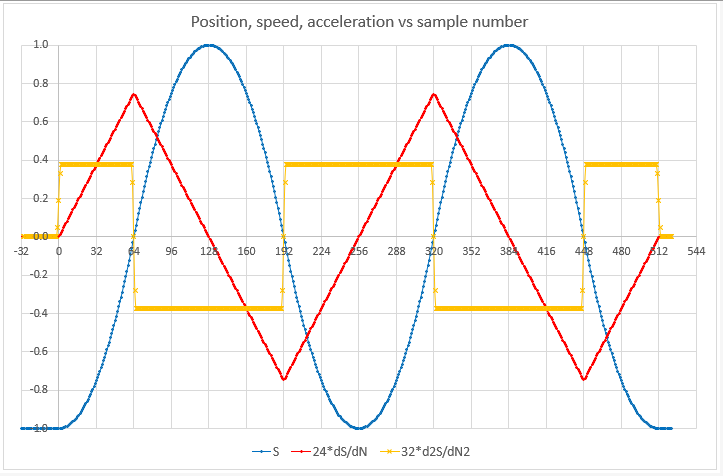
To get constant acceleration we apply a current waveform derived from the spreadsheet data to the loudspeaker coil, as shown in this figure. The waveform will also have a small error signal at 256 times the fundamental frequency, but this is easily filtered out with the RC low pass filter shown in the diagram.

The arduino PWM output produces a pulse train with an amplitude of 5V. The pulse train is filtered by R1 and C1 to produce an analog voltage. The corner frequency is fc= 1/2 pi() R C.
If we choose a wave with a frequency of 4Hz the error will be at 1024 Hz. An fc of about 64 Hz is 4 octaves away from 4, and also 4 octaves from 1024Hz so will give good filtering with little effect on the amplitude of the desired 4Hz signal.
We can use values of R1=2k7 and c=1uF.
If we measure the distance x the cone moves we can use the equation W = F x to calculate the work done by the force in moving the cone. Then if this repeats n times per second the power E needed is E = n F x watts.
We can then measure the current drawn by the circuit and the size of the applied voltage to measure the power. We determine the current through the loudspeaker by measuring the voltage across R2 with one of the arduino's analog inputs, and measure the collector voltage on TR1 with a resistive divider of 20k:10k to another analog input. That will tell us the amplitude of the voltage waveform across LS1.
Arduino Pulse Width Modulation (PWM)
The default frequency at which the Arduino produces a PWM output is only 976 (or 488) Hz. If we want to apply a 10Hz wave to the speaker we need at least 256 * 10 = samples per second - i.e. 2560Hz. And to allow at least 4 PWM waves in each sample we need a PWM rate exceeding 10kHz.
To achieve this we need to directly access the registers that control PWM - the Timer registers. There is an excellent page describing the Timer registers and fast PWM here.
As we dont expect great precision its sufficient to use 10 bit PWM. We can configure Timer1 to provide a phase correct PWM signal on pin D9 or D10. We choose a clock prescaler factor of 1, which gives us a clock frequency of 16MHz and a PWM frequency of 16000/512 = 31.25kHz
Excel spreadsheet to generate a sine wave