
John Errington's Experiments with an Arduino
Build an accurate Horticultural Moisture Meter
I've been using a cheapo moisture meter to check whether plants in pots needed watering. I have not been greatly impressed - mainly because it indicates the soil moisture at a point, rather than the general moisture content. 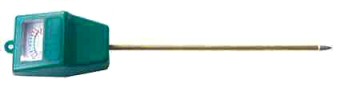
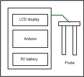
So I decided to build my own, using two probes to determine the resistance of the soil. The meter would consist of an Arduino with an I2C LCD display, and operate from a 9V battery.
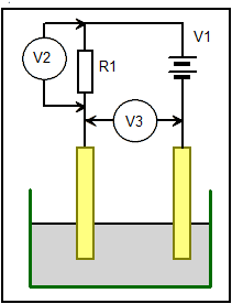
This diagram shows the simple way of measuring resistance between two probes. We need to know the values of R1, V1 and EITHER V2 OR V3.
Passing a direct current as shown above will cause the probes to corrode, so I decided to use an alternating current system, using two Logic outputs from the arduino, and two Analog inputs to measure the voltage difference. This required that the external circuit was symmetrical - otherwise a slightly simpler configuration could have been used.
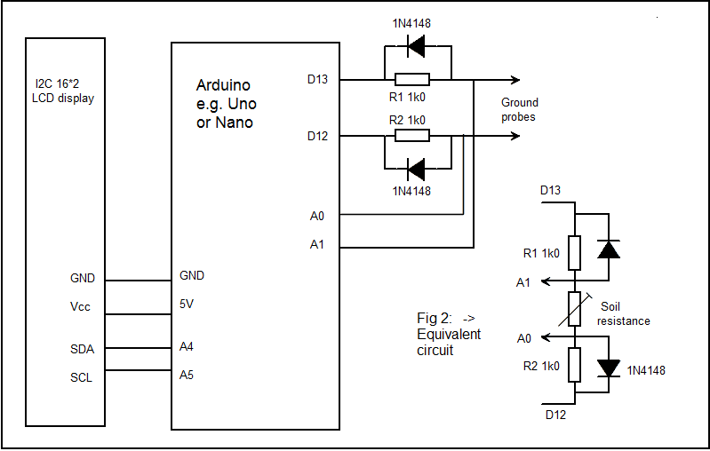
The diagrams above show the connections to the Arduino, and the method used for measuring soil resistance.
Suppose we set D13 to "HIGH" and D12 to "LOW". From the data sheet we see that when supplied with 5V an output pin can source 5 mA at about 4.9V; and sink 5 mA at 0.1V; The maximum current that can flow in our external circuit occurs when the "soil resistance" is 0. D12 will be at 0.1V and A0 at around 0.1 + 0.7V = 0.8V (allowing for the forward resistance of the diode). So A1 will also be at 0.8V and the maximum current through R1 will be
I=V/R = (4.9 - 0.8) = 4.1V /1k0 = 4.1mA - which is a very safe level for the Logic pins.
With an open-circuit between the probes A0 will read 0V and A1 +5V.
With the probe connected and in the soil we measure the voltages at A0 and A1. Since we know the voltages on D13 and D12, and the resistances in the circuit we can work out the resistance Rx between the probes. The system is most sensitive when Rx is the same as R, so we keep this as low as possible without drawing excessive current from the logic outputs (1k).
We now repeat the measurement with D13 "LOW" and D12 "HIGH". In both cases we take the absolute value (i.e the positive difference) between A0 and A1 as an indicator of the soil resistance.
Since there is the same current flow for the same time in both directions there is no net electrolytic effect.
Programming the nano
I found if in " board" I chose the nano I got "an error occurred while uploading the sketch", with 10 "not in sync" messages.
The problem was fixed by choosing "Duemilanove or Diecimlia" instead.
Program design
Initialize LCD and set Digital pins as outputs;
Set outputs for forward measurement (D13 HIGH D12 LOW)
Read voltage across probes
Set outputs for reverse measurement (D13 LOW D12 HIGH)
Read voltage across probes
Calculate saturation
Print result to LCD.
Repeat.
Sketch
The sketch is developed to show how integer arrays can be used, and also passing parameters to and from functions.