John Errington's Experiments with an Arduino
Improved precision and accuracy from your ADC readings
Digital filter to reduce noise
Why take multiple readings
You may wonder why many example programs read the SAME ADC pin a few times. This is because
- electrical noise may be causing slight differences in your reading.
- the voltage you are reading may be changing.
- the voltage reference may be changing - especially the "DEFAULT" from your USB supply, or if you're using a battery.
By taking a SET of readings and averaging them you get more sensible results.
While you CAN take steps to reduce the noise in your system, noise isnt ALWAYS a bad thing.
Using noise to our advantage - It sounds strange but you can use the noise to give BETTER readings!
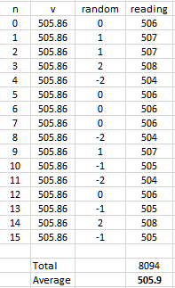
Suppose we have a 10 bit ADC reading a voltage of 2470 mV with a 5000 mV refererence. The reading SHOULD be 505.86 (505 or 506)
 Here we see the results of having a small amount of random noise in the reading. Each reading on its own shows a little "jitter". Taking a single reading we could see 504 or 508 as our result.
By taking 16 readings and averaging them CORRECTLY as shown here we see a more precise value.
EXAMPLE: our Arduino uses the "DEFAULT" reference of 5V from the USB connection.
So the measurement range is 0 - 5000 mV in 1024 steps. To find the voltage we add 0.5 then multiply our reading by 5000/1024
Our lowest reading of 504 gives 504.5 * 5000 / 1024 = 2463.37890625 ?
NO. The result CAN NOT be more precise than the data!
We have three figure precision in our data (0 - 1024) so we need to round the result to three figures. 2460mV
(We can be a LITTLE more precise; The resolution is 1 part in 1024 - or about 1/1000 so the result is 2463 +- 3 mV)
Taking 16 readings gives us extra resolution of two more bits (taking the 10 bit ADC to 12 bits)
(The formula is extra bits = sqrt(number of readings)/2) so 4 readings adds 1 bit, 16 adds 2, and so on.)
So our result of 505.9 gives V = (505.9 + 0.5) * 5000 / 1024 = 2473 mV
REFERENCE: Very good article here https://www.microchip.com/content/dam/mchp/documents/OTH/ApplicationNotes/ApplicationNotes/doc8003.pdf
Sketch to show oversampling in operation
The sketch follows the example above, and takes a set of 16 readings, averages them, and scales the result to mV.
Smooth the reading with a digital filter
If noise is causing a problem and all you want is a smooth response to an input signal you can use a very simple calculation.
This implements a "low pass filter" that will reduce the "jitter" in your readings
Its based on the idea that for an input signal that has noise, the best indicator of the true value is the current reading ; and the next best is the one before that. You can see how it works if you look at what happens when there is a sudden change at the input.

Here you see a signal that has suddenly changed from 136 to 0.
We are using a filter that calculates
new fValue = (old fValue *weighting) + (ADC reading * (1-weighting));
Its very easy to implement in your sketch.
This is just like a simple CR filter.
The "time constant" T is where the level falls to 0.368 of the change (here the 50 level) so for this weighting its about 4t (where t is the time between readings)
so as we would expect, the "output" (filter value) reaches the new input value after 5 time constants.
In the sketch the time between readings is set to 100msec, so on the "time" axis 10 represents 1 second.
This means the new value will not be fully shown until 4t * 5 * 100msec, or 2 seconds.
You can adjust the speed of the response by changing the weighting (a) or the interval between ADC readings.
How to choose a suitable weighting?
So our algorithm is Vnew = ( Vold * a) + ( ADC reading * (1-a))
You can work with the adc reading, Vold and Vnew raw, (thats easiest) or convert each to a voltage before filtering.
You MUST use floats or you will introduce rounding errors.
The value of the time constant is T = - 1 / ln (1-a); here is a table of values

You can see a larger value for a gives a longer time constant.
The 5T value is useful - it shows how long a change will take before the output level shows the new value.
So with a=0.6 the change will take 10t to show fully.
The time constant also tells you the "* cut off frequency" f0 of this as a low pass filter.
* the cut-off frequency is the frequency below which the signal is passed. Above that frequency the signal is reduced, by 20dB per decade.
If we are sampling at 10ms intervals with an "a" value of 0.6 then
T = 6msec and f0 = 0.166kHz
Sketch to show the filter in operation
The sketch follows the example above, implementing a simple "Infinite Impulse Response (IIR) digital filter.
Improving accuracy
Precision and accuracy are NOT the same. Our example above shows 4 figure precision - or actually 1 part in 4096.
We are using the DEFAULT reference - ie the "5V" supply.
Suppose the USB voltage was 4.800V (4800mV ); (that is WELL within the specification for USB.)
Our result of 505.9 leads us to believe the measured voltage was 2473mV. (above)
However we should really have taken V = (505.9 + 0.5) * 4800 / 1024 = 2374mV
The result was PRECISE - but not ACCURATE.
Its not possible to improve the accuracy beyond that internal to the converter; the best we can do is to compare it with a good reference voltage.
Calibration against a reference voltage at the ADC input
 Many newer boards, using chips such as the 32U4, ESP8266 and ESP32 dont provide a pin to apply an external reference. We can use a simple "trick" to get around this.
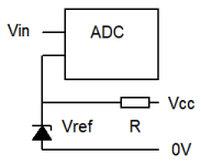
The idea is that the INTERNAL reference should not change much in a short period of time. So if we take a set of readings of Vin, as described above, using any available reference; then read Vref against the SAME reference, we can use the Vref reading to apply any necessary correction to our measurement.
You will of course need to choose a voltage reference within the range of the ADC. The LM4040AIZ-2.048 provides a voltage of 2.048V and you will need to choose a suitable resistor as shown above.
For a 3.3V supply a resistor in the range 4k7 - 47k should be fine, as the ADC input draws little current.
External Analog to Digital converters
The ADS1015 module offers 4 12 bit analog inputs and connects to the arduino via I2C. However the ADC is not a successive approximation type, but a Sigma-Delta converter.
This achieves high resolution (lots of bits) - but at the expense of much slower conversion rates.
