John Errington's Data Conversion Website
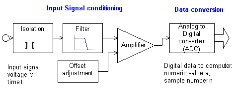
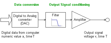
Complete system showing all components for signal input and output

Figure 1: shows all the usual component sections of a data acquisition system:

Figure 2: shows sections that may be used to produce an analog signal output
Example questions:
1) Discuss the problems inherent in measuring analog signals with a computer.
2) Definitions of terms.
a) Explain what is meant by gain error, offset error and non-linearity in a DAC.
b) A 12 bit bipolar ADC has a measurement range of -10V through 0 to +10V. Determine the resolution in volts.
3) Explain with the aid of appropriate diagrams the purpose of each of the modules in figure 1.
4) During crash testing of vehicles a sensor gives an output in the range 0.040 to 0.050 volts. The signal is to be measured to an accuracy of 1 part in 1000, with a sampling rate of 10,000 samples per second.
a) What type of ADC would you choose from the following list, and why?
Integrating, successive approximation, flash.
b) explain how you would condition the signal to match the 0 to 10V input range of the ADC. (10 marks)
5) An 8 bit DAC is to be used to generate a wave for testing church bells. The wave is to be sinusoidal in form, with a frequency in the range 100 to 10,000 Hz, and amplitude of 10V peak. If the wave is generated using 50 samples per period, sketch the size and frequency of error signals when a 100Hz wave is being generated.
