John Errington's Data Conversion Website
Data conversion
Data acquisition and data processing are increasingly important as more complicated tasks are delegated to computers. These require the data from the real world to be transformed into numbers for the computer, and later restored from digital to analog form. The devices that perform this conversion are called Analog to Digital converters (ADC) and Digital to Analog converters (DAC)
1: Digital data domain inside computer |
2: changing data inside computer |
 |
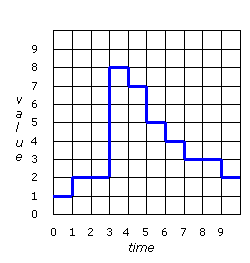 |
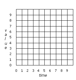
| A computer stores data as binary values. The smallest change that can occur is one bit. We say the computers data domain is quantized in both value and time dimensions. | Here you can see that the data can only change from one value to another at particular instants defined by the system clock |
3: An analog signal |
4: measuring an analog signal |
 |
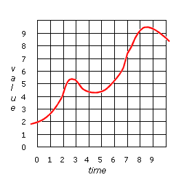 |
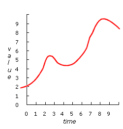
| Data in our world is often analog. It can change continuously by infinitely small amounts. | We prepare this data for the computer by measuring it at regular intervals, mapping it to the computer's data domain using an ADC |
5: digital representation of signal |
6: analog representation of signal |
 |
See diagram to left
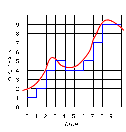
If this data is now sent out through a DAC the output voltage will follow the blue line almost exactly. It usually needs to be smoothed out before being used. For example if the output were used to control the position of a crane jib, the jib would move about erratically, with huge accelerations as it tried to get from one position to another instantly. This would be both wasteful of energy and damaging to the crane. The signal needs to be smoothed out. |
Above you can see the result of this measurement process. We now have a digital data stream that the computer can accept. However it is not a perfect copy of the analog signal. Write down the data values that the computer would read in. |
|
7: how the signal is smoothed |
8: smoothed signal |
 |
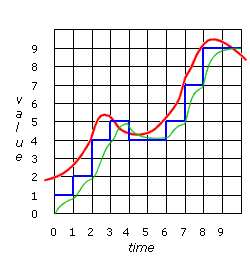 |
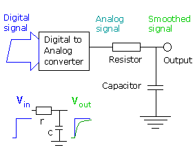
| This smoothing can be done by a simple circuit called an RC filter. It's shown in the diagram above. When a step signal is applied to the input of the filter a rounded 'exponential' signal appears at the output, as shown in the lower part of the figure. The result of using a filter like this is shown in fig 8.
|
Above you see the smoothed output (green line). Usually when we attempt to restore data from a set of measurements there is a loss of accuracy. You can see that the green line which represents the data restored to analog values doesn't match the original signal exactly. Make a note of the differences you can see. |
