John Errington's Data Conversion Website
Choosing ADC's and DAC's
In converting between analog and digital domains errors are introduced. The conversion system must be carefully designed to suit the nature of the signals to prevent these errors affecting the validity of the data. Let us look at the more difficult case, of converting from analog to digital data. We need to decide:
- The range of the allowed input signal,
- the smallest change that we need to measure, (the resolution) and
- how often the signal must be measured (sampling frequency).
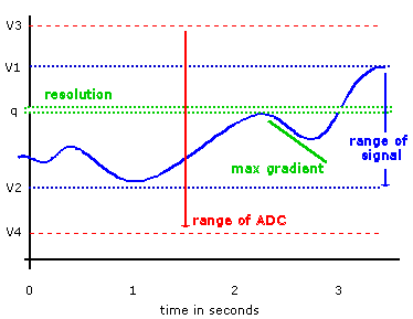
Here the signal is represented by the solid blue line. During the period shown the signal has a range of (v1 - v2) volts. To be certain that the signal will never exceed our ability to convert it we choose a converter with a greater range, say (v3 -v4) volts.
The resolution is the smallest measurable change (q). Suppose we are measuring room temperature, with a range of zero to 30 degrees. We might decide we need to measure to a resolution of half a degree.
We choose the sampling frequency to suit the fastest changing part of the signal (i.e. maximum gradient as change in volts/time).
These decisions will allow us to choose a converter appropriate to our needs.
Here is a more detailed analysis that allows us to choose ADC's and DAC's for irregular or "stochastic" signals. (pdf)
Errors in ADC's and DAC's
ADC's and DAC's are subject to the same types of errors. Consider the process of conversion from digital to analog. The ideal is that the output voltage is exactly uniquely and linearly dependent on the applied number, i.e.
Vout = k*n or Vout = ( k*n ) - a for a bipolar converter.
Here you can see this ideal conversion for a unipolar converter shown in blue, and some of the possible error types that can occur.
For most commercial converters the maximum value of error is less than the resolution of the device and can generally be ignored. However you should at least be familiar with the terms.
A potential source of more serious error, not caused by the ADC or DAC itself, can be seen in the page on sampling rate.
Choosing an ADC or DAC
The choice of a DAC is usually limited to the number of bits required, as all DACs are quite fast.  We know how many bits of data we are using, and the range of voltage we require. Measuring a changing voltage is a much different problem.
range and resolution
Having identified the range we require and the resolution to which we must measure tells us the number of bits required. For example to measure a signal with a range of 20V to a resolution of 0.1V requires 20/0.1 = 200 levels. We need an 8 bit converter, which gives 28 = 256 levels.
bipolar or unipolar
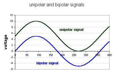
ADC's and DAC's are referred to as unipolar if the signal always has the same polarity, i.e. lies between zero volts and some other voltage. Bipolar signals are usually symmetrical about zero as shown here.
