John Errington's tutorial on Power Supply Design
Ripple current
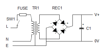
Remember our circuit for a smoothed 12V 2A dc power supply. TR1=12V rms, Vf for REC1 = 2V, C1=10mF
Rload = 6 ohms and Rint TR1 = 0.5 ohms
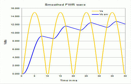
We found these waveforms in our supply.
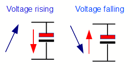
The capacitor acts to store charge when the voltage rises, and releases it when it falls.
During the time when the voltage from the transformer is low all the load current is supplied by the capacitor.
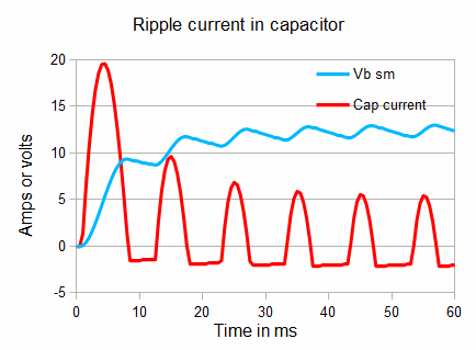
This means there is an AC current through the capacitor - the "ripple current".
This ripple current causes heating in the capacitor, and over time can be destructive. For high power PSU's we may need to determine the ripple current.
Here the RMS ripple current is 3.0 A
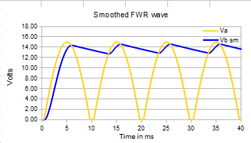 If the internal resistance of the transformer is low the shape of the ripple wave becomes more like a sawtooth.
Here the transformer internal resistance is set as 0.1 ohm
The RMS value of the output is slightly higher (13.7V) and the regulation (ie the change in voltage with load) is improved.
However the ripple current also changes.
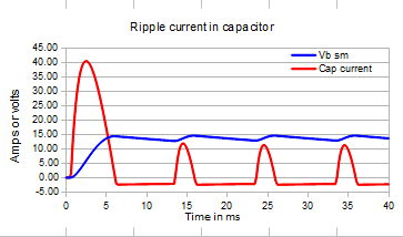
Even though the load has remained the same, the behaviour of current through the capacitor has changed dramatically. The current pulses are shorter and more triangular in shape.
The RMS value of ripple current is now 4.4A and the initial current pulse has doubled in size.
Example:
Remember our previous example: Design a Power supply to the following specifications:
Output voltage 24V ± 20 % at 5A with maximum ripple voltage of 4V peak - peak.
We chose a 3300uF capacitor, which using Vpk - pk ripple= Iload / 4fC gives
Vpk - pk ripple= 5A / 4*50*0.033 = 5/0.66 = 7.6V
Calculating ripple current
This is not straightforward. It depends on the effective internal resistance of the transformer/rectifier combination, the frequency, the maximum load, and the capacitance value.
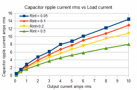
As a guide you can take the capacitor ripple current as being twice the load current.
The effective internal resistance of the transformer/rectifier combination can be measured in the usual way, by applying different loads around the design value and plotting the voltage and current. The slope gives the internal resistance. (OK its not truly linear, but just take a value).
You can then plot graphs and determine the RMS voltage and ripple current by putting your values into
this spreadsheet.
