John Errington's tutorial on Power Supply Design
High voltage
All the circuits previously described can easily be modified to be used with high voltages (say 50V - 400V)
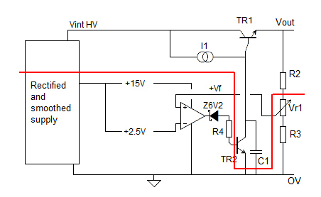
Look at the diagram below.
Simplified diagram for high voltage supply
 All the components below the red line are operating at low voltages -
in the region of 0 - 15V.
The only components where high voltages are present are the transistors TR1 and TR2, the capacitor C1, and the top resistor in the divider chain.
Although the regulator (or resistor) used to provide current to the base of TR1 is at a high positive voltage, it is not connected to ground, so the voltage across it is not a concern.
Choice of HV components
These should be chosen to withstand the voltages (and currents) that could arise. So TR1, C1, R2 and TR2 should be rated higher then the maximum voltage from the unregulated supply.
WHY?
Suppose you need a supply to provide 300V at 0.1A, and the unregulated supply provides 320V at 0.1A. At first sight you say - "we need TR1 with Vceo max> 320 - 300 = 20V." However if the load is capacitive, at switch on Vout = 0V, and Vceo = 320V.
Similarly, all components should be insulated to withstand these voltages. This is a particular concern when mounting the transistors on a heat sink, especially if the heat sink is earthed.
With high voltage supplies its important to check the power ratings of the components -see below.
Remaining components
The remining components all operate from a low voltage supply of around 15V - 24V. Its inefficient to provide this from the unregulated HV supply, so a separate low voltage unregulated supply will be needed. This is often sourced from a separate secondary winding on the transformer.
Example design
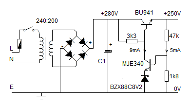
 This example shows a supply designed to provide 250V DC. The Zener diode is chosen because its temperature coefficient of +0.03%/C balances the -0.028%/C tpc of the transistor Vbe.
The base voltage is set to 8.2+0.7 = 8.9V which gives an output voltage of Vout = 8.9 * (47+1.8) / 1.8
Vout =
246V
This can be adjusted if necessary by trimming the 1k8 resistor with a higher value (around 220k) in parallel.
Power ratings
The power dissipation should be checked as HV supplies can cause higher powers to arise. For example consider the 47k resistor in this circuit.
V = 240V I = 5mA Pt = 1.2 watts. A 2W resistor (or better) is required so it runs cool.
The MJE340 is passing 9mA and has 250V across it. Pt = 2.4W
(its rated at 300V & 20W but will still need a small heat sink.)
