John Errington's tutorial on Power Supply Design
Current sources
Their place in a voltage regulated supply
Series regulators for supplies with variable outputs face a particular problem. The input voltage must be higher than the maximum required output voltage plus the insertion loss for the circuit. This means when the lowest output voltage is selected, Vin>>Vout. Since Vreg follows Vout the current through R - which supplies our voltage reference - alo changes dramatically.
 Lets take the example of our previous design. Vin = 36V. Vout = 20 - 30V.
Suppose R=100 ohms and Vreg = Vout + 1.4V.
IRmin = 36 -
(30 + 1.4) / R IRmin = 4.6V /1k = 4.6mA
IRmax = 36-(20+1,4) / R
IRmax =14.6V / 1k = 14.6mA
We could improve this situation by making Vin larger - but this just wastes energy as unwanted heat, and increases component costs.
We can overcome this problem by replacing the resistor R with a current source. There are many different configurations we could use, but some of the simpler, economical and effective types are described here. One factor to note is the insertion loss for the circuit, which we will need to keep to a minimum.
Simplest circuit
 Current flows through resistor R and D1 setting a voltage across Vbe and Re.
The voltage across Re is then VD1 - Vbe, and iRe =
VD1 - Vbe / Re
If TR1 has a large Hfe Iout = IRe = VD1 - Vbe / Re
Limitations: as the output load changes the voltage across TR1 and its power dissipation changes. This will cause Vbe to change, and Iout will change. We can compensate this by adding a diode in series with D1 and attaching it to TR1 so their temperatures are the same.
Insertion losss is VD1. We can minimise this by using a low voltage zener, an LED or a pair of diodes to set the base voltage.
Using a regulator IC
 This circuit works in the same way as the one above. The LM317 is a variable voltage regulator that can supply up to 1.5A. The adjsut pin is used to set the required voltage. In this configuratiion it sets the voltage across R1 to 1.25V. The drop-out voltage is around 2.0 - 2.5V
A better circuit
 Current flows through R into the base of TR1, allowing current to flow through Re to Iout. If the current gets too high, TR2 turns on and robs TR1 of base current. This is an excellent way of either making a current source or of limiting the available current to a defined maximum value.
Iout = Vbe(TR2) / Re
Because the voltage across TR2 is limited to 2*Vbe little power dissipation occurs, so Vbe is more stable.
Drop-out voltage is around 2*Vbe
Current mirror
 This circuit is called a "current mirror". Provided the transistors used are identical, the collector current for TR2 will be the same as that for TR1. However, whatever the physical characteristics of the transistors, Iout will always be proportional to i1.
Additional transistors (TR2a, TR2b, TR2c etc) can be wired across TR2 to give crrent multiplication.
Drop-out voltage is around 1.0V.
A VERY simple (but not very accurate) current source
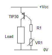 If Vcc is approximately constant we can build a very simple current regulator around a single PNP transistor, as shown here.
Example: the TIP30 transistor has an HFE of 15 - 75, and can supply a collector current of 1A (with a suitable heat sink).
Say we want a current of 300mA and Vcc is 12V : choose a resistor R1 to limit the base current to 300/15 = 20mA. (12V / 20mA = 0.6k; use 620 ohms.)
Now choose a trimpot VR1 in series with R1 to limit the base current to 300/75 = 4mA. (12V / 4mA = 3k. We need 3k - 0.62k so choose a 2k7 or 2k2 trimpot)
Place a current meter in place of the load (or in series with it) and adjust VR1 so the load current is 300mA.
Drop-out voltage is less than 1.0V.
NB: HFE is temperature dependent; this circuit is more a current limiter, not an accurate current source, but WILL provide overcurrent protection in simple circuits.